Convertible Roof that Latches to an Upper Transverse Frame Part of the Windshield Frame

a technology of windshield frame and convertible roof, which is applied in the direction of carpet fasteners, dwelling equipment, applications, etc., can solve the problems of insufficient space in some vehicles, substantial construction space required for this type of roof construction, etc., and achieve the effect of high stability of roof securing arrangemen

a technology of windshield frame and convertible roof, which is applied in the direction of carpet fasteners, dwelling equipment, applications, etc., can solve the problems of insufficient space in some vehicles, substantial construction space required for this type of roof construction, etc., and achieve the effect of high stability of roof securing arrangemen

US20080290688A1Inactive Publication Date: 2008-11-27WILHELM KARMANN GMBH

Image

  • Convertible Roof that Latches to an Upper Transverse Frame Part of the Windshield Frame
  • Convertible Roof that Latches to an Upper Transverse Frame Part of the Windshield Frame
  • Convertible Roof that Latches to an Upper Transverse Frame Part of the Windshield Frame

Examples


Embodiment Construction

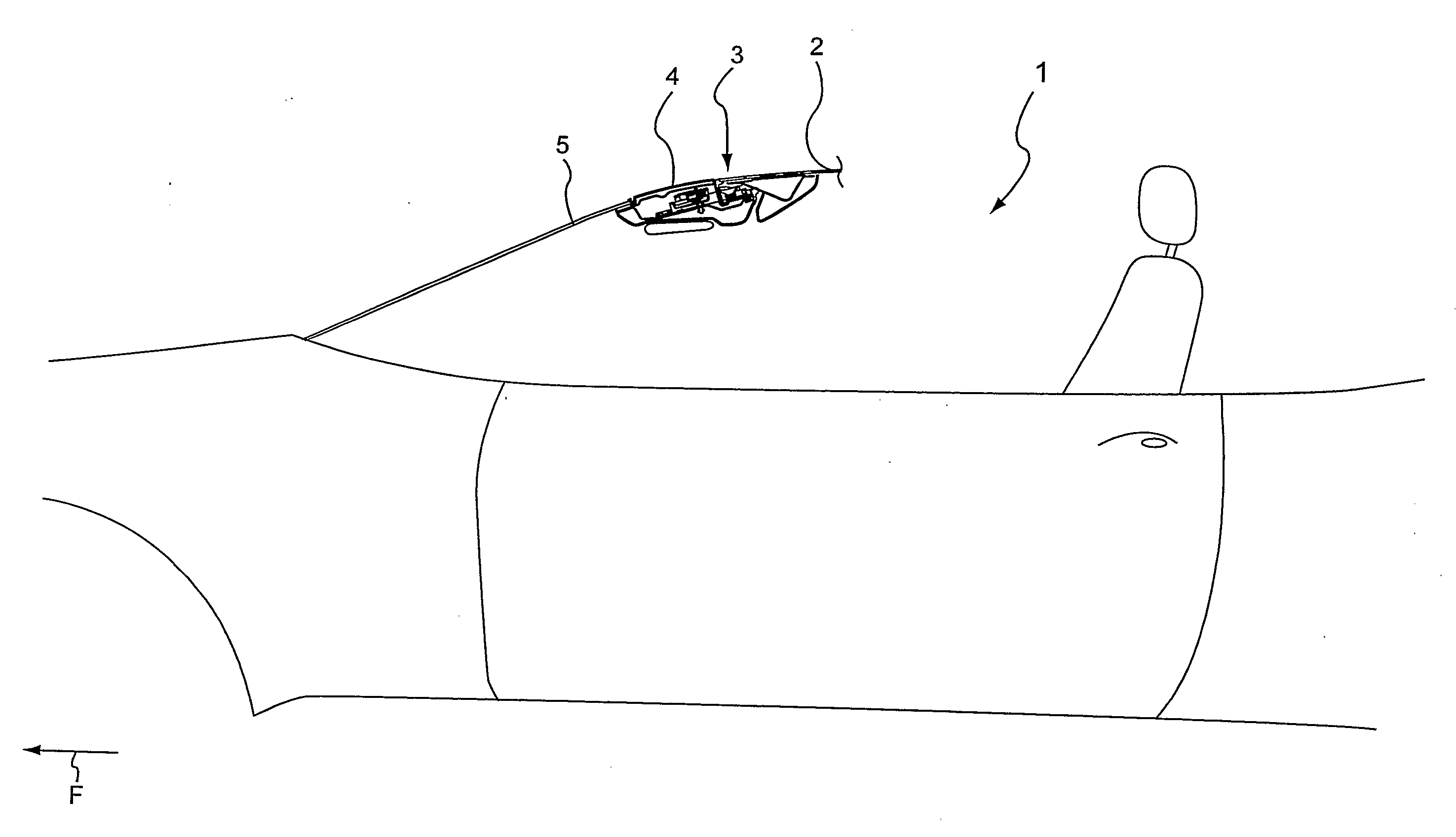
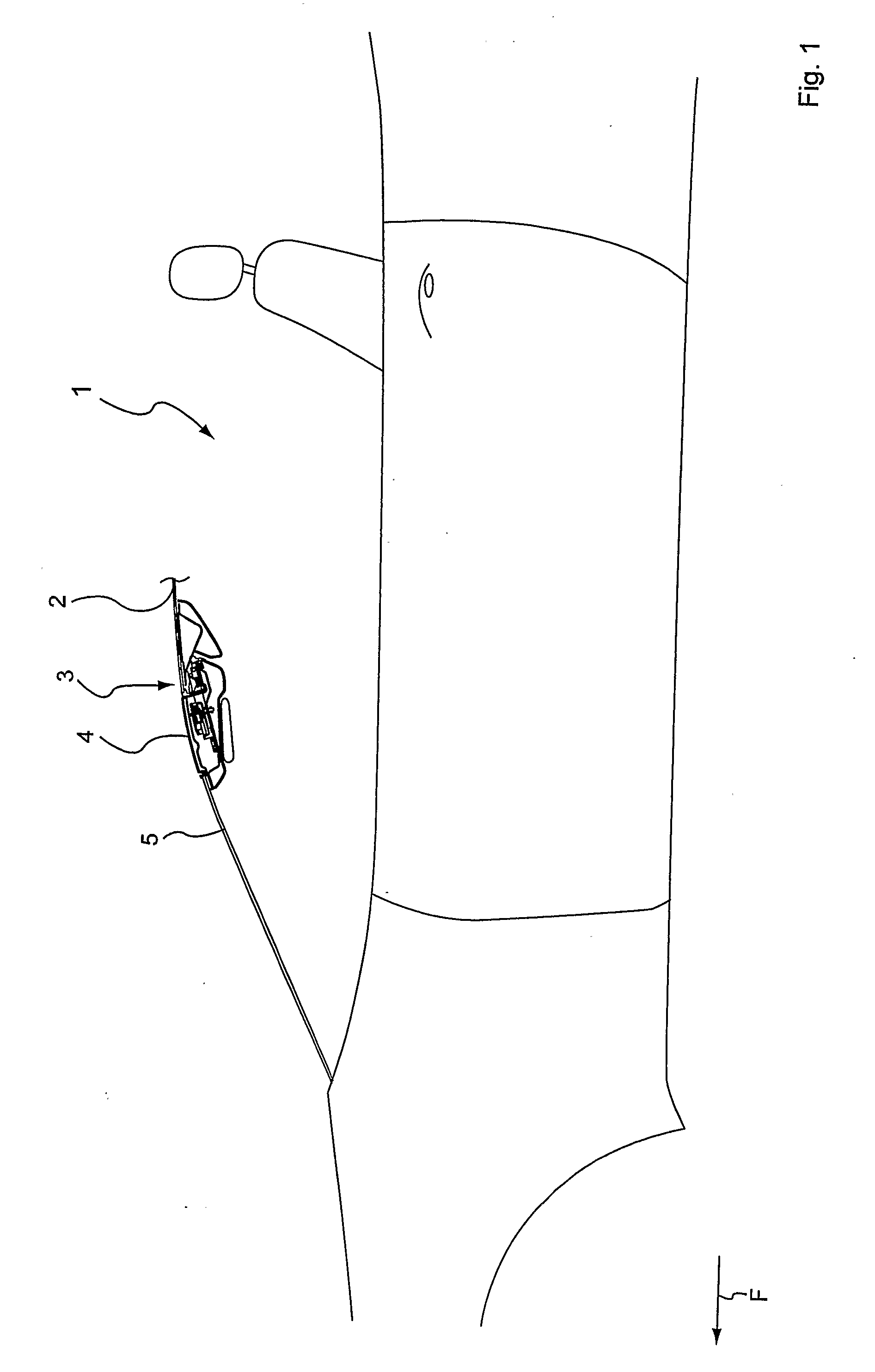
[0035]The convertible vehicle 1, which is only partially shown in the drawing, comprises a movable roof 2 that can be configured, for example, as a retractable hardtop (RHT) or as a soft top with a front end 3 of the roof that is rigid.

[0036]It is understood that the roof shape and the vehicle size can be made differently. For example, the convertible vehicle 1 can be either a two-seater or a convertible vehicle with a larger passenger space and, for instance, two or more rows of seats behind one another.

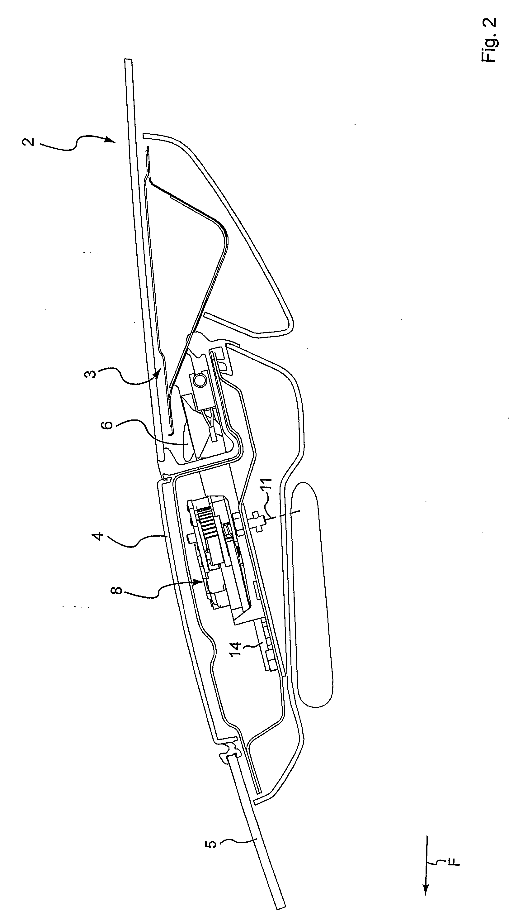
[0037]As shown in FIGS. 1-3, the front end 3 of the roof, also called a roof tip, is latched to an upper crossmember 4, frequently also called a cowl or a header, of a frame enclosing the windshield 5. At least one moving hook part 6 is provided which can secure a latch 7 of the roof tip 3.

[0038]For this securing or release of the latch 7, the at least one hook part 6 can be moved linearly in the upper cross-frame part 4. In the illustrated embodiment, two hook parts 6 are provided ...


PUM


Abstract

A convertible vehicle according to the present invention includes a vehicle body with a windshield frame with an upper transverse frame part. A convertible roof for the vehicle has a front end. At least one hook part is disposed in the upper transverse frame part and is linearly movable in the upper transverse frame part

Description

REFERENCE TO RELATED APPLICATIONS[0001]This application is the United States national phase application of PCT / DE2006 / 001142, filed Jul. 1, 2006, which claims priority from German patent application No. DE102005034726.6, filed Jul. 21, 2005, the entire content of both of which are incorporated herein by reference.FIELD OF THE INVENTION[0002]The invention relates to a convertible vehicle comprising a roof which can be secured in its closed position to an upper transverse frame part of the windshield frame.BACKGROUND OF THE INVENTION[0003]The front end or tip of a convertible roof is typically latched to the windshield frame using closing members when the roof is closed. Typically, hook parts and aligning centering spigots are provide on the front end of the roof. The hook parts drop into corresponding recesses of the windshield frame and cooperate with latches provided in the windshield frame. The latches typically pivot to engage the hook parts.[0004]It is desirable to reduce the we...

Claims


Application Information

Patent Timeline
27 Nov 2008
Publication
US20080290688A1
IPC
B60J7/08
CPC
B60J7/1851; Y10S292/05
Inventors
BROCKHOFF, FRANZ-ULRICH