Retinal array compound camera system having at least three imaging sensors

a camera system and camera technology, applied in the field of remote imaging techniques, can solve the problems of large scale factor, inefficiency of systems, and challenge even the most robust imaging system, and achieve the effect of small image distortion and wide collective fov of the target area

Inactive Publication Date: 2008-11-27
VI TECH LLC
View PDF55 Cites 6 Cited by
  • Summary
  • Abstract
  • Description
  • Claims
  • Application Information

AI Technical Summary

Benefits of technology

[0009]The present invention provides an imaging system having a compound array of imaging sensors disposed such that their focal axes converge, intersect, and thereafter diverge. Individual imaging sensors can be disposed within a housing or a host craft in a concave or retinal configuration, with non-coinciding lines of sight. Depending upon the configuration of the housing or host craft, a small aperture, portal or iris may be formed in the housing, and the array positioned in relation to the aperture, portal or iris, such that the point of intersection of the focal axes coincides with the aperture, portal or iris—the size of which can thus be minimized. Thus, a small aperture in the housing or craft may provide optical access to the target area for a large number of sensors. The individual sensors are disposed, and may be selectively adjusted, to have adjoining or overlapping lines of sight within the target area, resulting in a wide collective FOV of the target area. The imaging array of the present invention thus provides images with very little image distortion. The present invention further eliminates the need for cumbersome, expensive primary lenses.

Problems solved by technology

A major challenge facing some such remote imaging applications is one of image resolution.
Depending upon the particular system used (e.g., aircraft, satellite, or space vehicle), an actual digital imaging device may be located anywhere from several hundred feet to several miles above its target, resulting in a very large scale factor.
Providing images with very large scale factors, that also have resolution tolerances of inches, poses a challenge to even the most robust imaging system.
Such systems are generally inefficient when images with wide FOV are desired.
Furthermore, such systems are usually very costly.
Rapid development of new sensor technologies renders these systems obsolete or requires that the systems have cumbersome and costly upgrades or modifications.
Although such a configuration can provide a wider FOV for imaging, it is still limited in application.
In many cases, however, large portal spaces are impractical, if not impossible, to provide within the small confines of a host craft.
Furthermore, larger portals allow a relatively high degree of light backscatter in the array, causing ghost images and degrading the overall quality and reliability of the images obtained.

Method used


Image

  • Retinal array compound camera system having at least three imaging sensors
  • Retinal array compound camera system having at least three imaging sensors
  • Retinal array compound camera system having at least three imaging sensors

Examples


Embodiment Construction

[0027]While the making and using of various embodiments of the present invention are discussed in detail below, it should be appreciated that the present invention provides many applicable inventive concepts, which can be embodied in a wide variety of specific contexts. The specific embodiments discussed herein are merely illustrative of specific ways to make and use the invention and do not limit the scope of the invention.

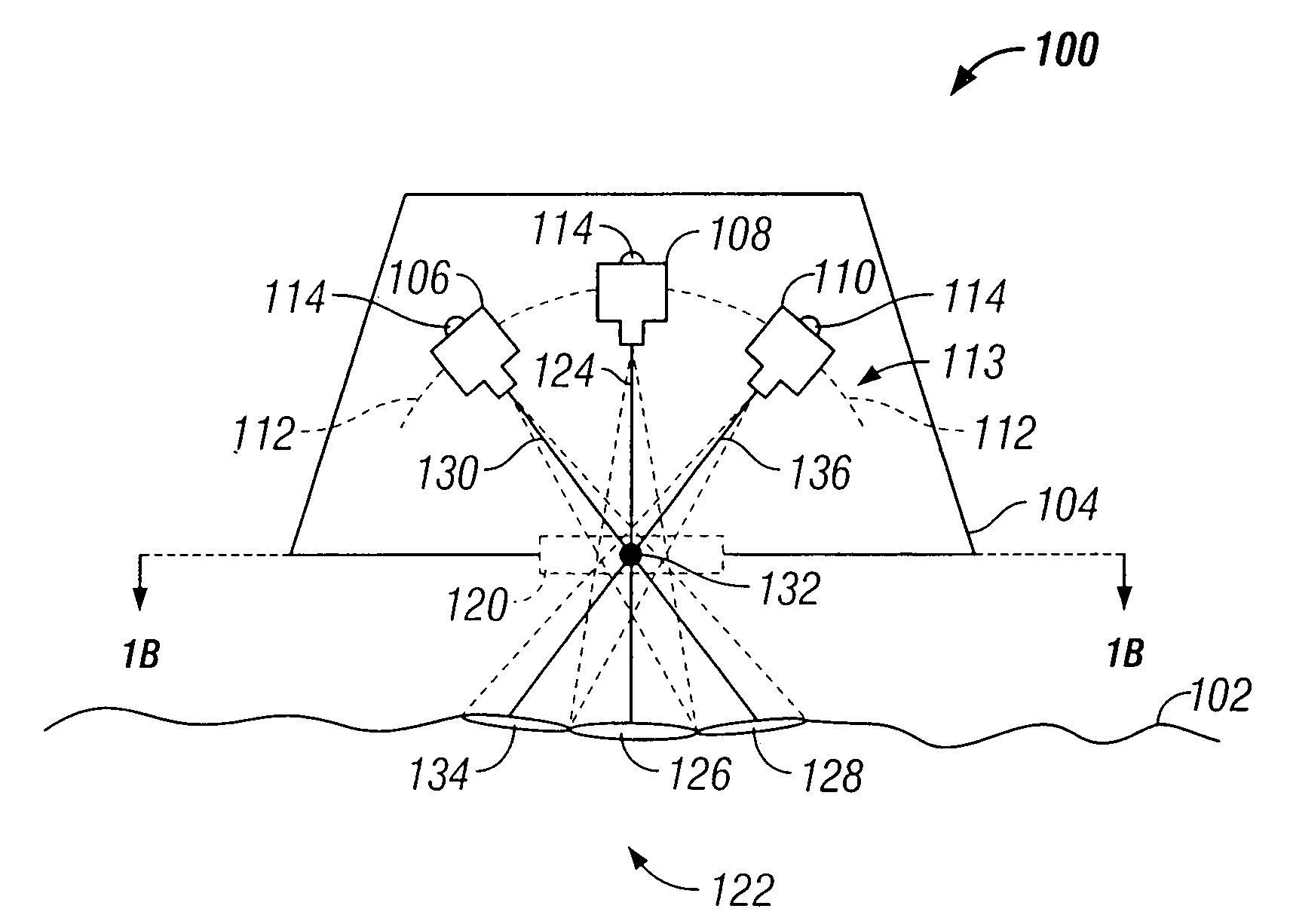
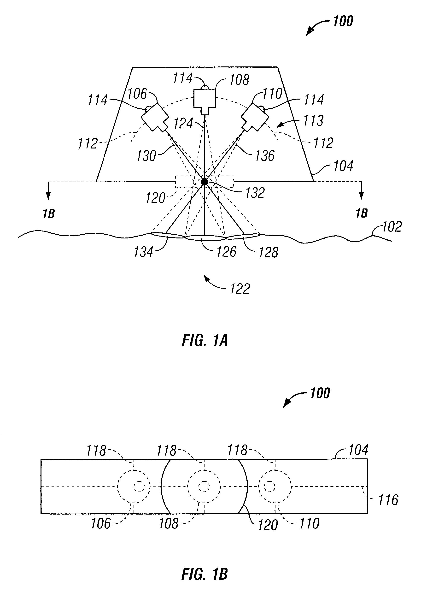
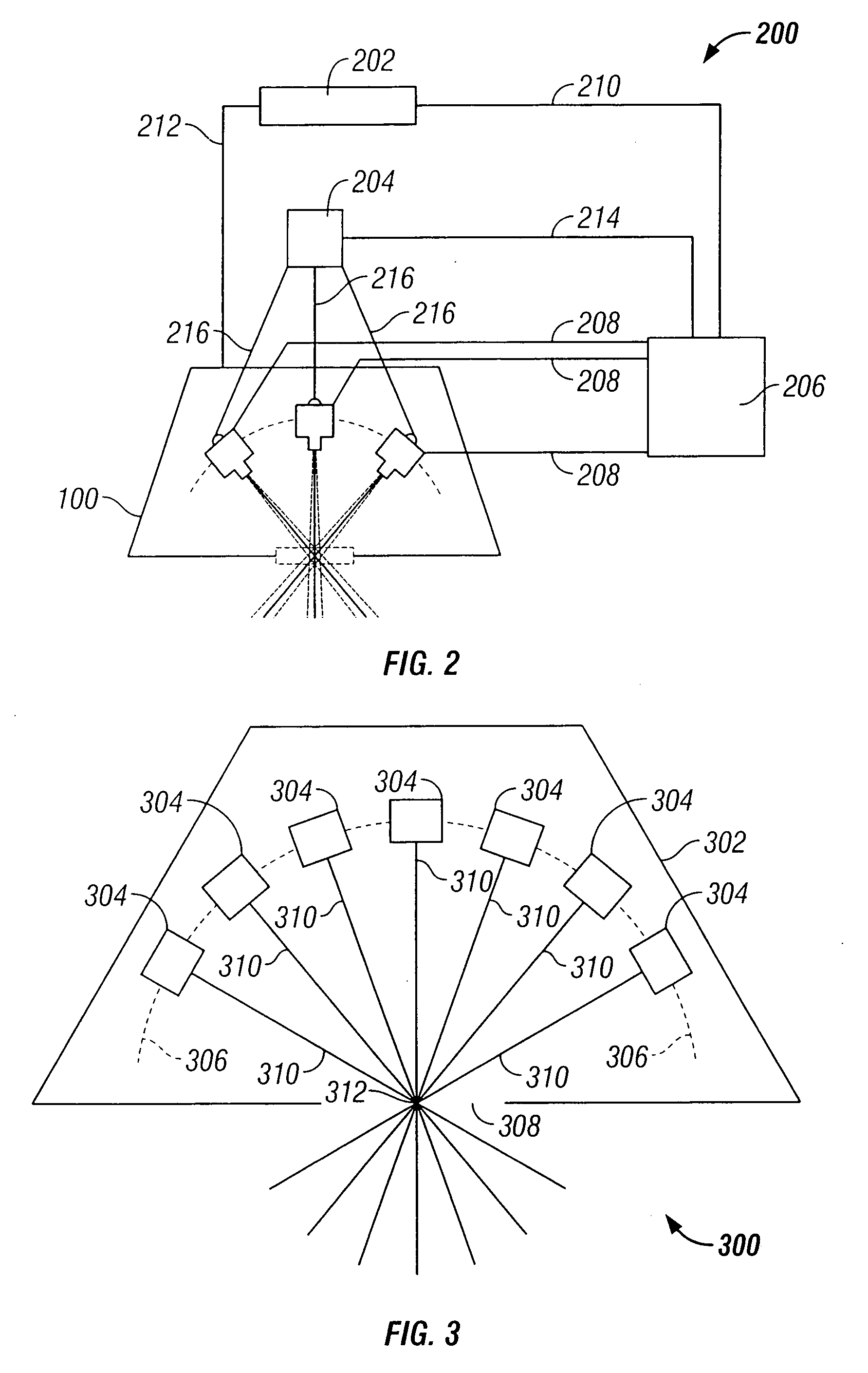
[0028]The preferred embodiment of the present invention provides an imaging system having a compound array of imaging sensors disposed such that their focal axes converge, intersect, and thereafter diverge. Individual imaging sensors can be disposed within a host craft in a concave or retinal configuration, with non-coinciding lines of sight. Depending upon the configuration of the host craft, a small aperture, portal or iris may be formed in the craft, and the array positioned in relation to the aperture, portal or iris, such that the point of intersection of th...


PUM


Abstract

The present invention provides a camera system having a compound array of imaging sensors disposed in a retinal configuration. The system comprises a concave housing. A first imaging sensor is centrally disposed along the housing. A second imaging sensor is disposed along the housing, adjacent to the first imaging sensor. The focal axis of the second imaging sensor intersects with the focal axis of the first imaging sensor within an intersection area. A third imaging sensor is disposed along the housing, adjacent to the first imaging sensor opposite the second imaging sensor. The third imaging sensor has a focal axis that intersects with the focal axis of the first imaging sensor within the intersection area.

Description

CROSS-REFERENCE TO RELATED APPLICATION[0001]This application is a divisional of prior U.S. application Ser. No. 10 / 229,626 filed on Aug. 28, 2002.TECHNICAL FIELD OF THE INVENTION[0002]The present invention relates, generally, to the field of remote imaging techniques and, more particularly, to an imaging system providing high-resolution digital imaging over very large fields of view.BACKGROUND OF THE INVENTION[0003]Remote imaging is a broad-based technology having a number of diverse and extremely important practical applications—such as geological mapping and analysis, military surveillance and planning, and meteorological forecasting. Aerial and satellite-based photography and imaging are especially useful remote imaging techniques that have, over recent years, become heavily reliant on the collection and processing of digital image data. Spatial data—characterizing real estate improvements and locations, roads and highways, environmental hazards and conditions, utilities infrastr...

Claims


Application Information

Patent Timeline
Patent Type & Authority Applications(United States)
IPC IPC(8): H04N7/18H04N5/225G01C11/02G03B37/00G03B17/56H04N5/232
CPCG01C11/025H04N5/23238H04N5/232H04N23/50H04N23/661H04N23/698H04N7/18H04N23/00
Inventor PETERS, III, LEO J.SMITHERMAN, CHESTER L.
Owner VI TECH LLC
Why Eureka
Try Eureka