Eureka AIR delivers breakthrough ideas for toughest innovation challenges, trusted by R&D personnel around the world.

Method and device for image measurement, exposure apparatus, substrate for image measurement, and device manufacturing method

Inactive Publication Date: 2008-11-27
CANON KK
View PDF3 Cites 2 Cited by
  • Summary
  • Abstract
  • Description
  • Claims
  • Application Information

AI Technical Summary

Benefits of technology

[0011]Accordingly, the present invention provides an aerial image measurement method and an aerial image measurement device capable of measuring an aerial image immediately and highly accurately.

Problems solved by technology

The evaluation method needs steps of resist application, development, and measurement, and hence, a single evaluation may take a long time, and need a large cost.
Unfortunately, with the above slit-scan method, when the pitch of variation in the intensity distribution of the aerial image 40 becomes short, the modulation factor of the slit-scan signal may be significantly degraded if the longitudinal direction of the slit 540 is shifted from a line-extending direction of the L / S pattern in the aerial image 40.
The modulation factor of the slit-scan signal becomes substantially zero, and hence, the measurement is no longer available.

Method used


Image

  • Method and device for image measurement, exposure apparatus, substrate for image measurement, and device manufacturing method
  • Method and device for image measurement, exposure apparatus, substrate for image measurement, and device manufacturing method
  • Method and device for image measurement, exposure apparatus, substrate for image measurement, and device manufacturing method

Examples


Embodiment Construction

[0029]Various embodiments, features and aspects of the present invention will now herein be described in detail in accordance with the accompanying drawings.

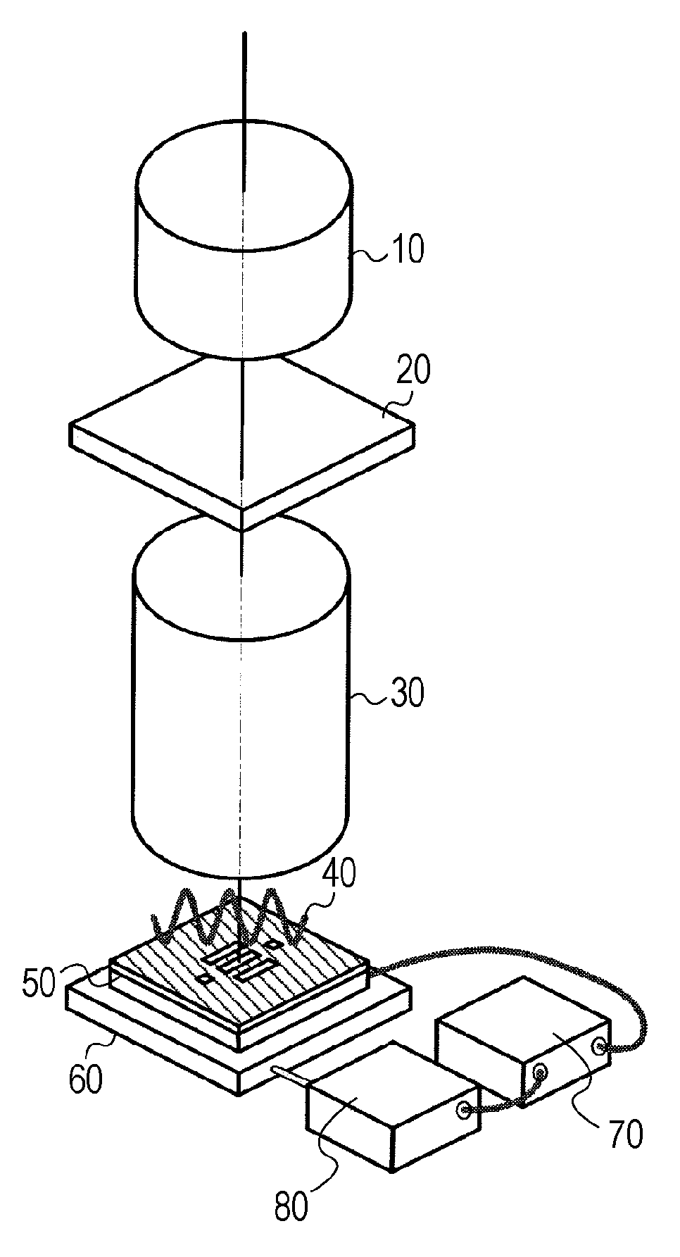
[0030]FIG. 1 is an explanatory view schematically showing a state of measuring an optical performance of a projection optical system in an exposure apparatus according to an embodiment of the invention. In the drawing, reference numeral 20 denotes a mask, 10 denotes an illumination optical system to illuminate the mask 20 with light from a light source (not shown), 30 denotes a projection optical system, and 40 denotes an aerial image. Reference numeral 50 denotes a sensor, 60 denotes a stage to drive the sensor 50, 70 denotes a signal processing unit to process a signal from the sensor 50, 80 denotes a drive unit (alignment unit) to drive the stage 60 in accordance with a signal output from the signal processing unit 70.

[0031]The illumination optical system 10 shapes light from the light source, and emits the shaped light on th...


PUM


Abstract

An image measurement method is provided for measuring an image of a pattern of a mask projected with a projection optical system. The method includes the steps of detecting light transmitted through an aperture while a substrate is arranged at an image plane of the projection optical system, the substrate having a slit and the aperture having a width larger than a width of the slit; adjusting an alignment angle of the slit on the basis of a signal related to the light detected in the detecting; and measuring the image by detecting light transmitted through the slit while moving the slit, the alignment angle of which has been adjusted in the adjusting, in the image plane of the projection optical system.

Description

BACKGROUND OF THE INVENTION[0001]1. Field of the Invention[0002]The present invention relates to an image measurement method, an image measurement device, an exposure apparatus, a substrate for image measurement, and a device manufacturing method.[0003]2. Description of the Related Art[0004]In order to evaluate the performance of a projection optical system of an exposure apparatus while the projection optical system is mounted on the main body of the exposure apparatus, a wafer coated with resist is generally used, and the wafer is exposed to a mask pattern. In this evaluation method, after the exposure, the resist is developed to form a resist pattern, and the resist pattern is measured with, for example, a scanning electron microscope (SEM). The evaluation method needs steps of resist application, development, and measurement, and hence, a single evaluation may take a long time, and need a large cost.[0005]Therefore, a measurement method has been performed in which an image of a ...

Claims


Application Information

Patent Timeline
IPC IPC(8): G03B27/72G01B11/00
CPCG03F7/70666G03F1/84
Inventor OHKUBO, AKINORI
Owner CANON KK
Why Eureka
Eureka Blog
Learn More