Vibration compensation for image capturing device

a technology vibration compensation, which is applied in the field of apparatus for compensating for vibration of image capturing device, can solve the problems of blurred image, degraded resolution and chromatism of projected image, and degraded resolution of projected image, so as to reduce power consumption, compact and lightweight image capturing device, and quality image

Inactive Publication Date: 2008-11-27
HYSONIC
View PDF5 Cites 23 Cited by
  • Summary
  • Abstract
  • Description
  • Claims
  • Application Information

AI Technical Summary

Benefits of technology

[0007]The present invention has been made in order to solve at least part of the problems in the art. It is an object of the invention to provide a simplified mechanical apparatus for moving the image sensor in a direction as to compensate for the vibration by hand-shaking, thereby resulting in quality image and reduced power consumption, and compact and lightweight image capturing devices.

Problems solved by technology

Typically, such small image capturing devices are portable and often cause blurred images due to inevitable hand-shaking.
Although different people have different degrees of hand-shaking, it consequently leads to a blurred image, due to unsteady focal point.
When the blurred image is projected onto a large screen, the projected image comes to have degraded resolution and chromatism, i.e., failing to have quality image.
However, the above electrical control has disadvantages of degraded resolution of image and narrow compensation range.
The mechanical approach must use a motor for driving the lens and the entire image capturing device, leading to a higher consumption of power and an obstacle to realization of compact and lightweight products.
Since light is refracted by acti-prism, it is resolved according to the wavelength of light, thereby incurring chromatic aberration.

Method used


Image

  • Vibration compensation for image capturing device
  • Vibration compensation for image capturing device
  • Vibration compensation for image capturing device

Examples


first embodiment

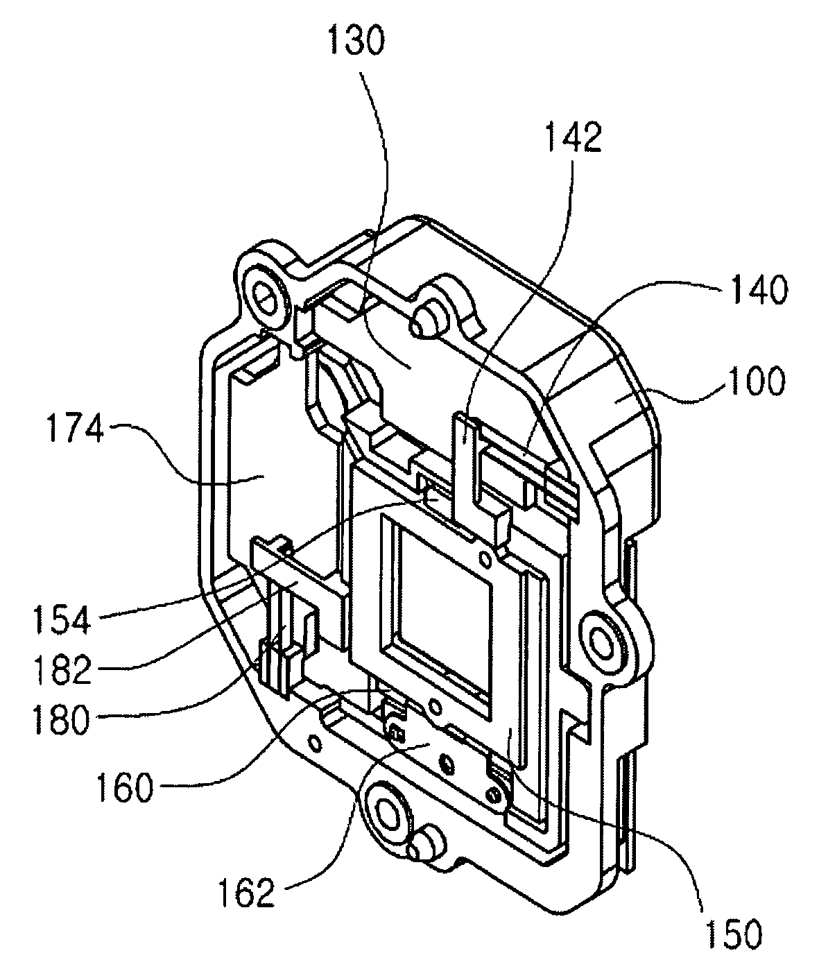
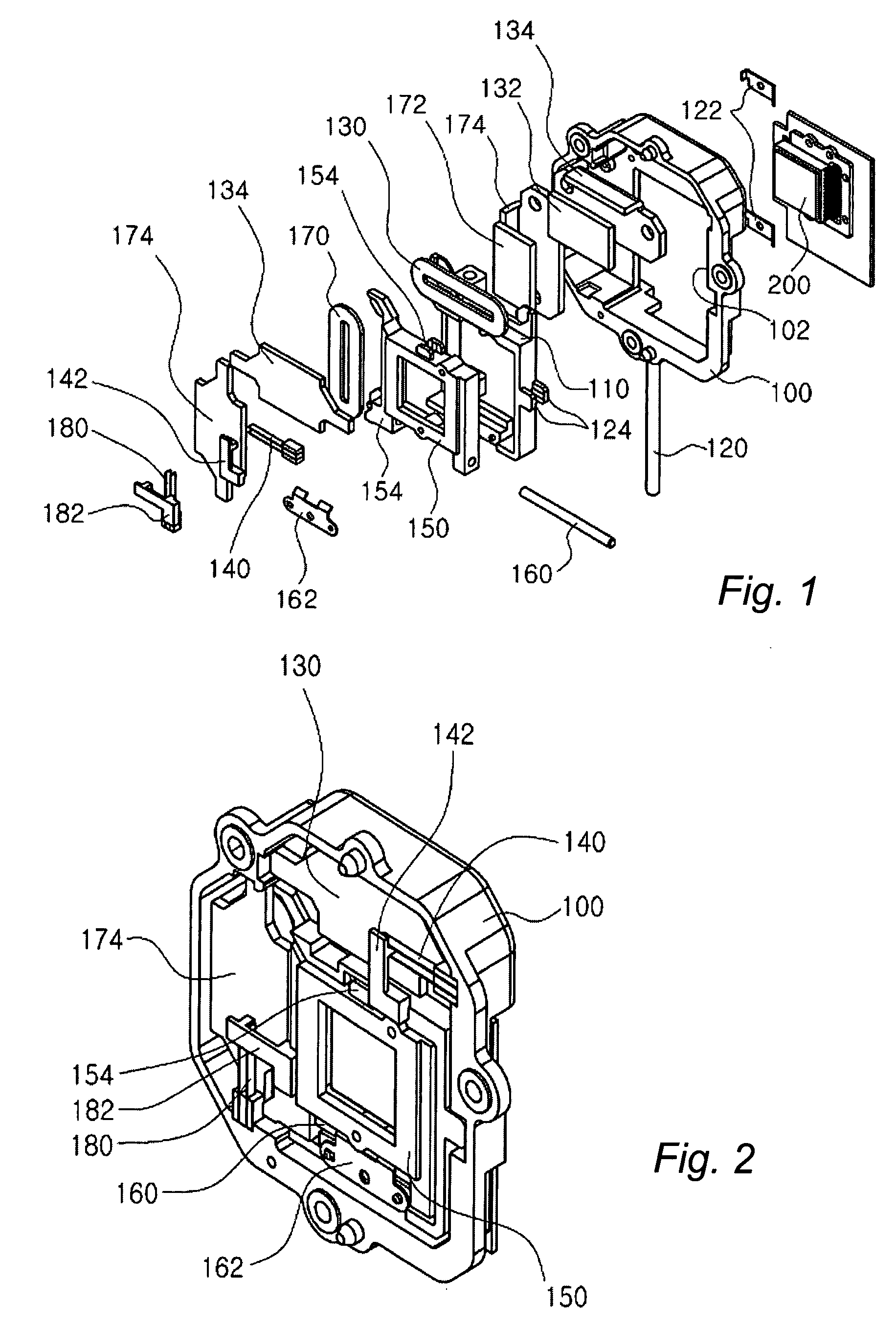
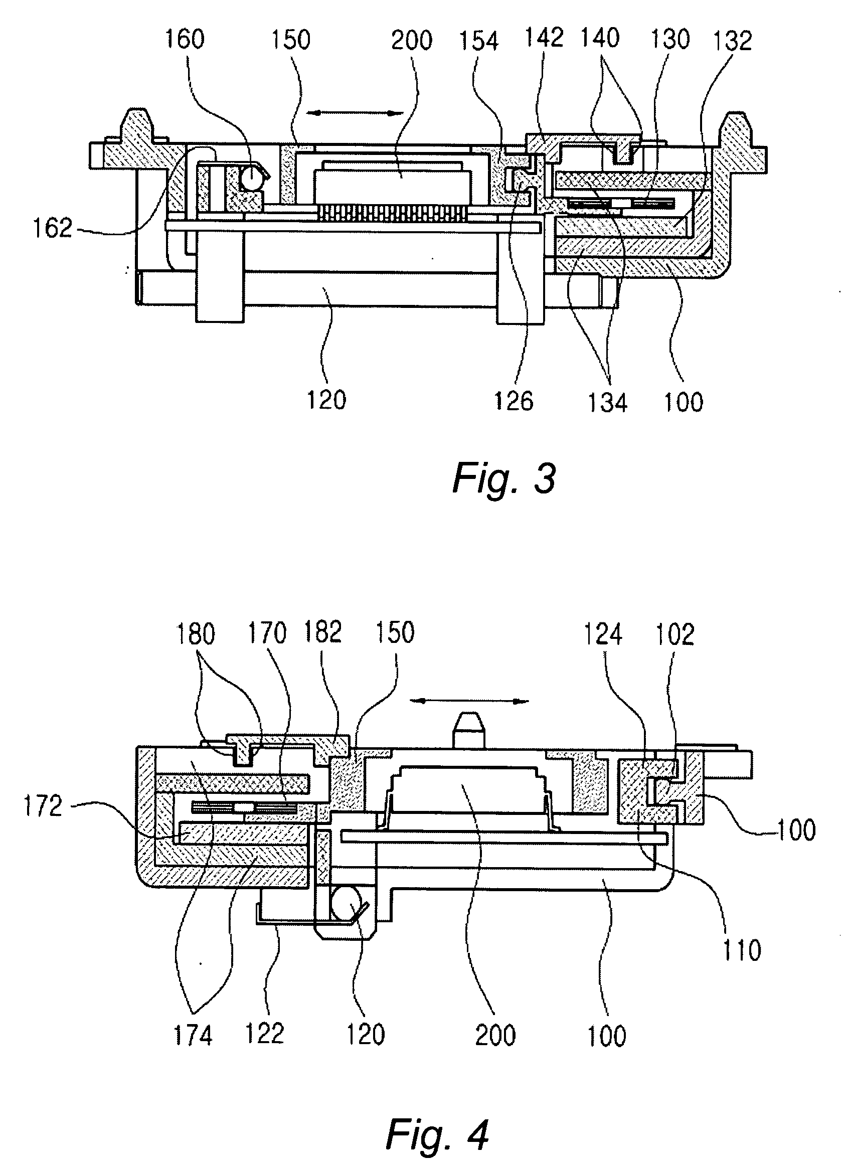
[0027]FIG. 1 is an exploded perspective view of a camera vibration compensator according to the invention. FIG. 2 shows the camera vibration compensator of FIG. 1 when assembled. FIG. 3 is a sectional view taken along the x-axis in the camera vibration compensator of FIG. 2. FIG. 4 is a sectional view taken along the y-axis in the camera vibration compensator of FIG. 2.

[0028]In this embodiment, the vibration compensator includes a base 100 that is to be fixed on an image capturing device such as a digital camera, a y-axis stage 110 installed in the base 100 so as to be movable in y-direction, and a y-axis driver for driving the y-axis stage 110 in the y-direction. Here, the base 100 can be replaced by any desired structural support. An x-axis stage 150 is installed on the y-axis stage 110 so as to be movable in the x-direction on the x, y-plane. An image sensor 200 is mounted on the x-axis stage 150. Alternatively, the image sensor 200 may be mounted on the y-axis stage 110. An x-ax...

second embodiment

[0090]Dissimilar to the above second embodiment, the stage 1220 is formed of a single stage and disposed inside of the housing 1210. An image sensor 1250 is mounted on the stage 1220.

[0091]The driver includes an x-axis driver for driving the stage 1220 in the x-direction and a y-axis driver for driving the stage 1120 in the y-direction.

[0092]The y-axis driver is composed of a first magnet 1221 fixed to the housing 1110, and a first coil 1222 fixed to the stage 1220. Here, it should be understood that the first magnet may be fixed to the stage and the first coil to the housing. The first coil 1222 has multiple windings and is disposed within the electromagnetic field of the first magnet 1221. When electric current is applied to the first coil, the first coil generates an electromagnetic force that interacts with magnetic flux of the first magnet 1221 to drive the stage 1220 in the y-direction. In addition, the y-axis driver includes a first yoke 1223 for concentrating magnetic flux o...


PUM


Abstract

Disclosed herein is an apparatus for compensating for vibration of an image capturing device. The apparatus includes a y-axis stage installed in a support structure so as to be movable in y-axis direction. An x-axis stage is installed on the y-axis stage so as to be movable in x-axis direction on an xy plane. An image sensor is mounted on the x-axis stage. The apparatus is provided with a y-axis driver and an x-axis driver for driving the y-axis stage in the y-axis direction and the x-axis stage in the x-axis direction respectively. A control unit is installed in the image capturing device. The control unit operates to sense vibration of the image capturing device through a separate vibration sensor and to drive the y-axis driver and the x-axis driver to vibrate the image sensor in a way to compensate for the vibration of image capturing device.

Description

FIELD OF THE INVENTION[0001]The present invention relates to an apparatus for compensating for vibration of an image capturing device, more specifically to such an apparatus for moving an image sensor in a way as to correct vibration by an unsteady hand to thereby prevent image blurring.BACKGROUND OF THE INVENTION[0002]In general, cellular phones capable of transmitting mobile images, image capturing devices such as digital cameras and camcorders, and the like are manufactured in compact and lightweight designs for the convenience of portability. These small-sized image capturing devices have functions of capturing images, and recording and reproducing the captured images, and have been widely popularized in recent years.[0003]Typically, such small image capturing devices are portable and often cause blurred images due to inevitable hand-shaking. Although different people have different degrees of hand-shaking, it consequently leads to a blurred image, due to unsteady focal point. W...

Claims


Application Information

Patent Timeline
Patent Type & Authority Applications(United States)
IPC IPC(8): G03B17/00H04N5/00
CPCG03B5/06H04N5/2253H04N5/23248H04N23/54H04N23/68
Inventor RYU, JAE WOOKLEE, YOUNG PYOKO, JOUNG SUK
Owner HYSONIC
Why Eureka
Try Eureka