
Multi-axis imaging system having individually-adjustable elements

a multi-axis imaging and individual adjustment technology, applied in the field of array microscope optical elements, can solve the problems of difficult to construct an array of lenses, degrade system performance, and difficult challenges, and achieve the effect of reducing the effect of spherical aberration and modifying image quality

Inactive Publication Date: 2005-01-11
DMETRIX INC
View PDF12 Cites 17 Cited by
  • Summary
  • Abstract
  • Description
  • Claims
  • Application Information

AI Technical Summary

Benefits of technology

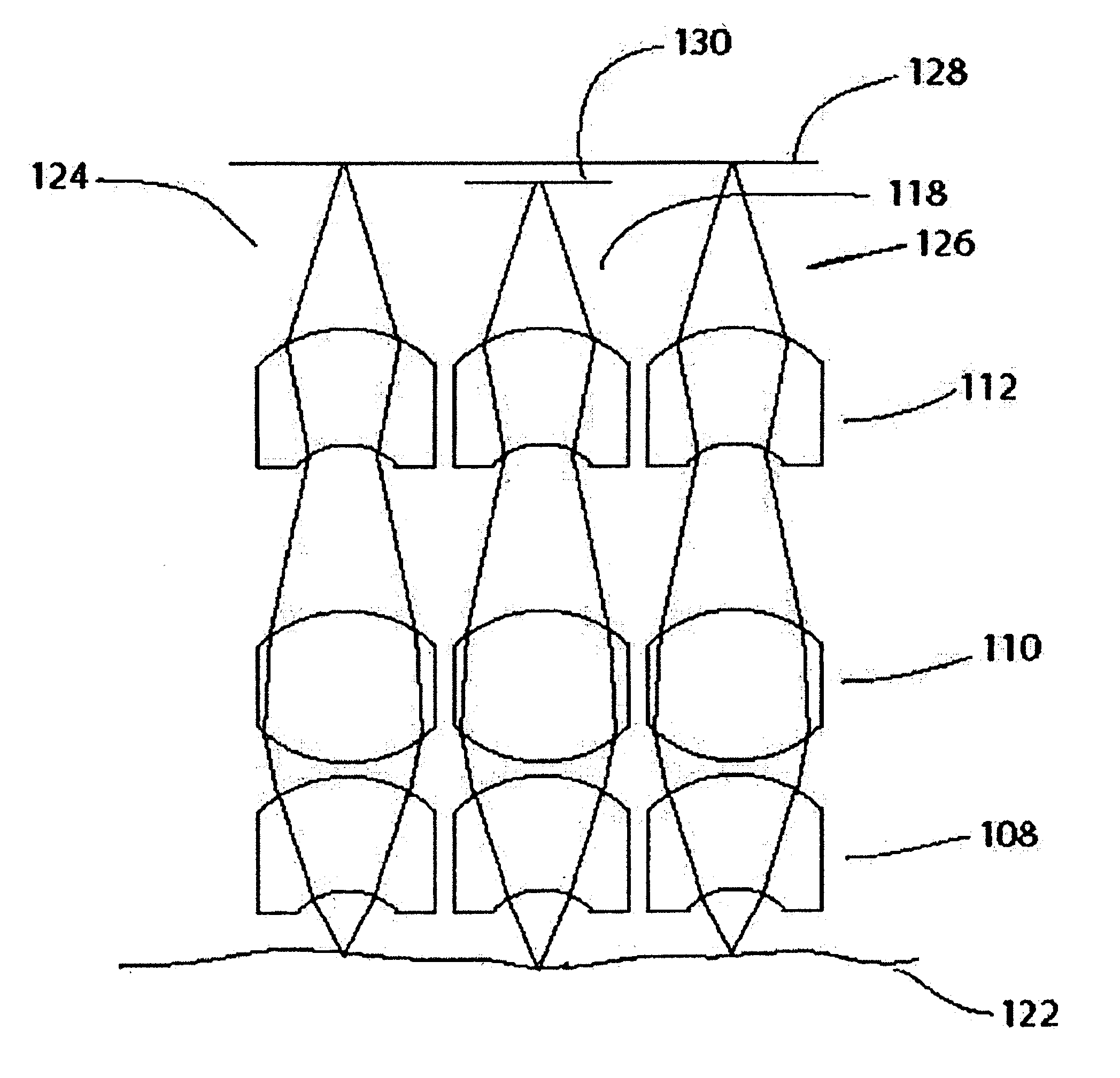
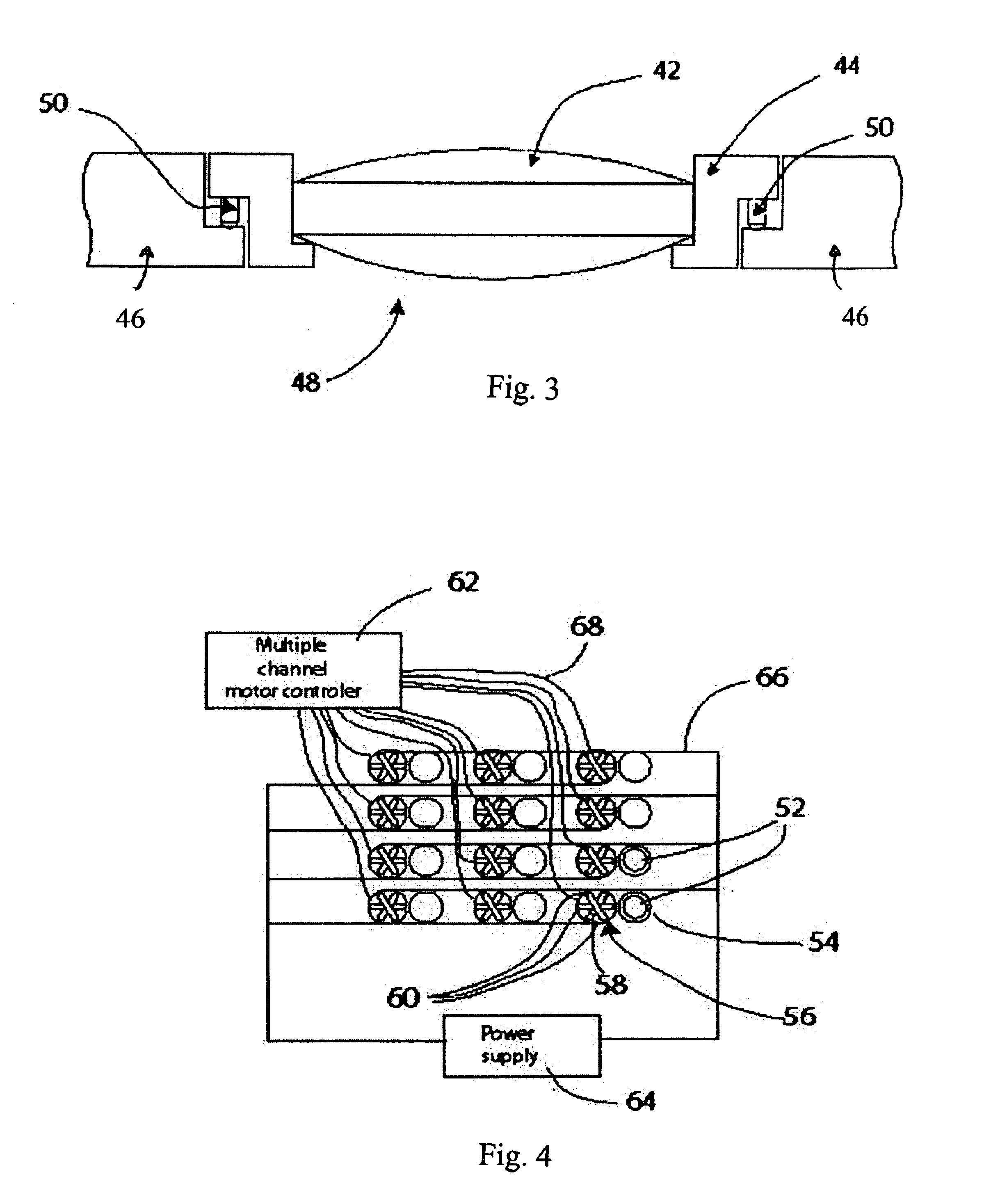
A method is provided for modifying the quality of images produced by a multi-axis imaging system having a plurality of optical elements and respective optical axes, comprising adjusting the positions of the optical elements individually with respect to their respective optical axes so as to modify their respective image qualities at a common image plane. The method includes adjusting the axial position, lateral position and angular orientation of the optical elements with respect to their respective optical axes to modify image quality. The method also comprises selecting and arranging the optical elements so as to perform as microscope elements. In accordance with the method, the axial position, lateral position and angular orientation of respective microscope elements may be individually adjusted with respect to the common image plane and their respective optical axes to compensate for fabrication and assembly errors in one or more of the microscope elements. The adjustments may be made by a predetermined amount based on one or more measured parameters of respective microscope elements, or they may be based on analysis of image quality in real to time. The adjustments may be made to change the working distance of the microscope to compensate for object irregularity, based on, for example, measurement of the surface profile of the object; to compensate for the thickness of an object; or to reduce the effect of spherical aberration of the microscope that contains said microscope element due to cover glass thickness variation.

Problems solved by technology

However, in a multi-axis imaging system, separate alignment of individual optical elements, and lenses within an optical element, is inherently counter to the concept of disposing the optical elements of an array in a fixed relationship so that that they can be moved in unison and, thence, presents a difficult challenge.
One such problem is that it is difficult to construct an array of lenses wherein all of the lenses are laterally spaced within an acceptable tolerance.
Consequently, random displacement of the images of respective elements may degrade system performance.
Another problem is that it is difficult to construct an array of lenses all of which are the same shape within an acceptable tolerance.
Again, random variation in lens shapes may degrade system performance.
A problem of particular importance in microscopes is that either the thickness of the glass slide on which a specimen is mounted, or the surface of the specimen itself, may be sufficiently non-uniform that the portion of interest of one portion of an object may lie outside the depth of field of the microscope when focused on another portion of the object.
However, in an array microscope the overall field of view may be such that, because of slide or object non-uniformities, portions of an object imaged by one set of optical elements may be in focus, while other portions of the object imaged by another set of optical elements are out of focus, thereby degrading the overall image of the object.

Method used


Image

  • Multi-axis imaging system having individually-adjustable elements
  • Multi-axis imaging system having individually-adjustable elements
  • Multi-axis imaging system having individually-adjustable elements

Examples


Embodiment Construction

Although the present invention may be applicable to a variety of multi-axis imaging systems, it is particularly advantageous in miniature microscope arrays wherein a plurality of miniature microscopes are arranged in an array and, heretofore, coupled so as to have a fixed relationship with one another. Accordingly, while the invention is hereafter described in terms of a miniature microscope array, particularly used as an array microscope, it is to be understood that any multi-axis imaging system may fall within the scope of this invention.

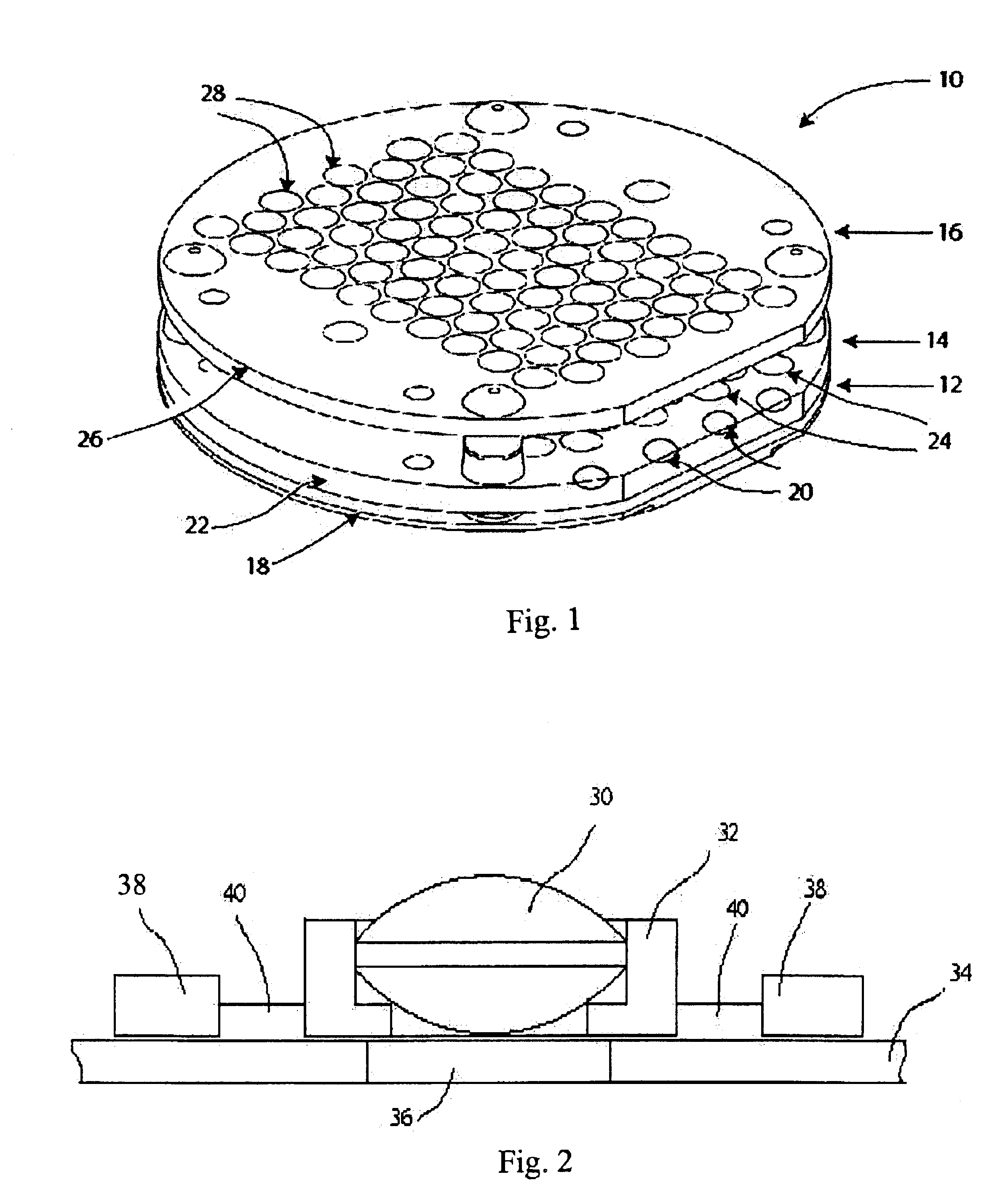
An exemplary miniature microscope array 10 is shown in FIG. 1. It comprises three sub-arrays, 12, 14 and 16, each comprising a substrate and one of three respective lenses for each of the optical elements of the microscope array 10. Thus, for each element of the microscope array, substrate 18 supports a bottom lens 20; substrate 22 supports a middle lens 24; and substrate 26 supports a top lens 28; and the respective lenses of each of the three su...


PUM


Abstract

A multiple-axis imaging system having individually-adjustable optical elements and a method for individually adjusting optical elements of the system. The system comprises a plurality of optical elements having respective optical axes and being individually disposed with respect to one another to image respective sections of an object, and a plurality of individually-operable positioning devices corresponding to respective optical elements for positioning the optical elements with respect to their respective optical axes. The positioning devices are specifically adapted to adjust the axial position, lateral position and angular orientation of the optical elements with respect to their respective optical axes. The system is particularly adapted for use as a microscope array, and the positioning devices may be micro-actuators.

Description

BACKGROUND OF THE INVENTIONThis invention relates to the adjustment of optical elements in a multi-axis imaging system, particularly the optical elements of an array microscope.In a multi-axis imaging system, as that term is used herein, a plurality of optical elements are arranged in an array so as to image respective portions of a common object. One advantage of such a system is that all of the elements of the array can have a fixed relationship to one another and may be moved in unison to scan an object and bring its image into focus at a desired image plane. In particular, in an array microscope an array of miniature microscope objectives is employed instead of a single objective to achieve high resolution, without the mechanical drawbacks of a single, equivalent objective, and to scan a large field of the object more rapidly than can be achieved with a single objective. Such an array microscope is disclosed in PCT Patent Publication No. WO 02 / 075370, published Sep. 26, 2002.The...

Claims


Application Information

Patent Timeline
Patent Type & Authority Patents(United States)
IPC IPC(8): G02B21/24G02B21/00
CPCG02B21/241G02B21/002
Inventor LIANG, CHENOLSZAK, ARTUR G.GOODALL, JAMES
Owner DMETRIX INC
Learn More