Video Transmitting Apparatus, Video Receiving Apparatus, Video Transmitting Method, and Video Receiving Method

a video transmitting and video receiving technology, applied in the field of video transmitting apparatus, video receiving apparatus video transmitting method, etc., can solve the problems of reducing the amount of code assigned to the p picture area p_mb and the reduction of image quality, so as to improve image quality, image quality is likely to decrease, and image quality is likely to improve

Inactive Publication Date: 2011-03-03
SONY CORP
View PDF8 Cites 20 Cited by
  • Summary
  • Abstract
  • Description
  • Claims
  • Application Information

AI Technical Summary

Benefits of technology

[0019]With this arrangement, according to the video receiving method in the embodiment of the present invention, the video transmitting apparatus can appropriately recognize that an error is detected. Thus, only when an error occurs, the video transmitting apparatus is caused to enter the propagation-prevention encoding mode in which the image quality is likely to decrease. Consequently, it is possible to improve the image quality when no error occurs.
[0020]According to the present invention, it is sufficient that, when an error occurs, the operation enters the propagation-prevention encoding mode in which the image quality is likely to decrease. Thus, it is possible to improve the image quality when no error occurs. Accordingly, the present invention can realize a video transmitting apparatus, a video receiving apparatus, a video transmitting method, and a video receiving method which can improve the image quality.

Problems solved by technology

Since a large amount of code is assigned to the I picture areas I_MB, there are problems in that the amount of code assigned to the P picture areas P_MB is reduced and the image quality is reduced.

Method used


Image

  • Video Transmitting Apparatus, Video Receiving Apparatus, Video Transmitting Method, and Video Receiving Method
  • Video Transmitting Apparatus, Video Receiving Apparatus, Video Transmitting Method, and Video Receiving Method
  • Video Transmitting Apparatus, Video Receiving Apparatus, Video Transmitting Method, and Video Receiving Method

Examples


first embodiment

1. First Embodiment

1-1: Configuration of Video Processing System

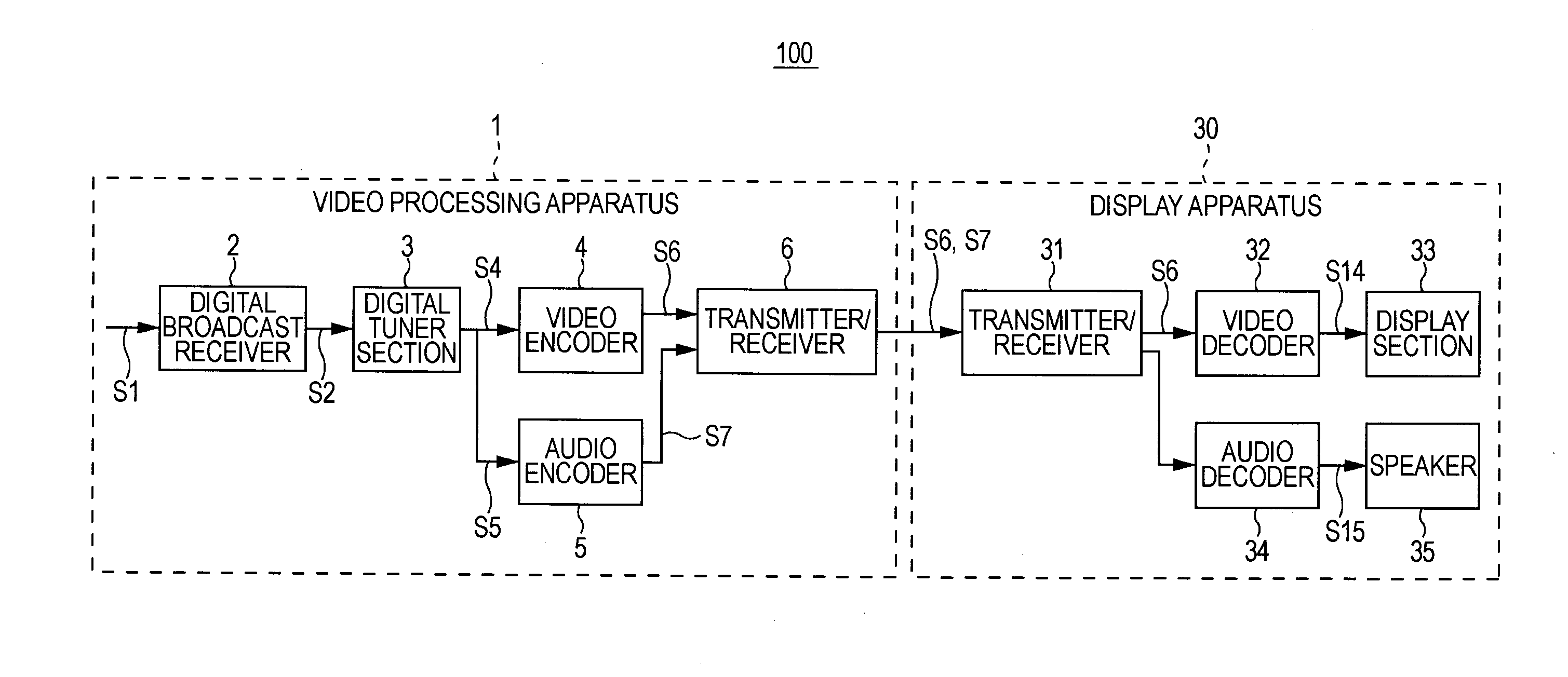
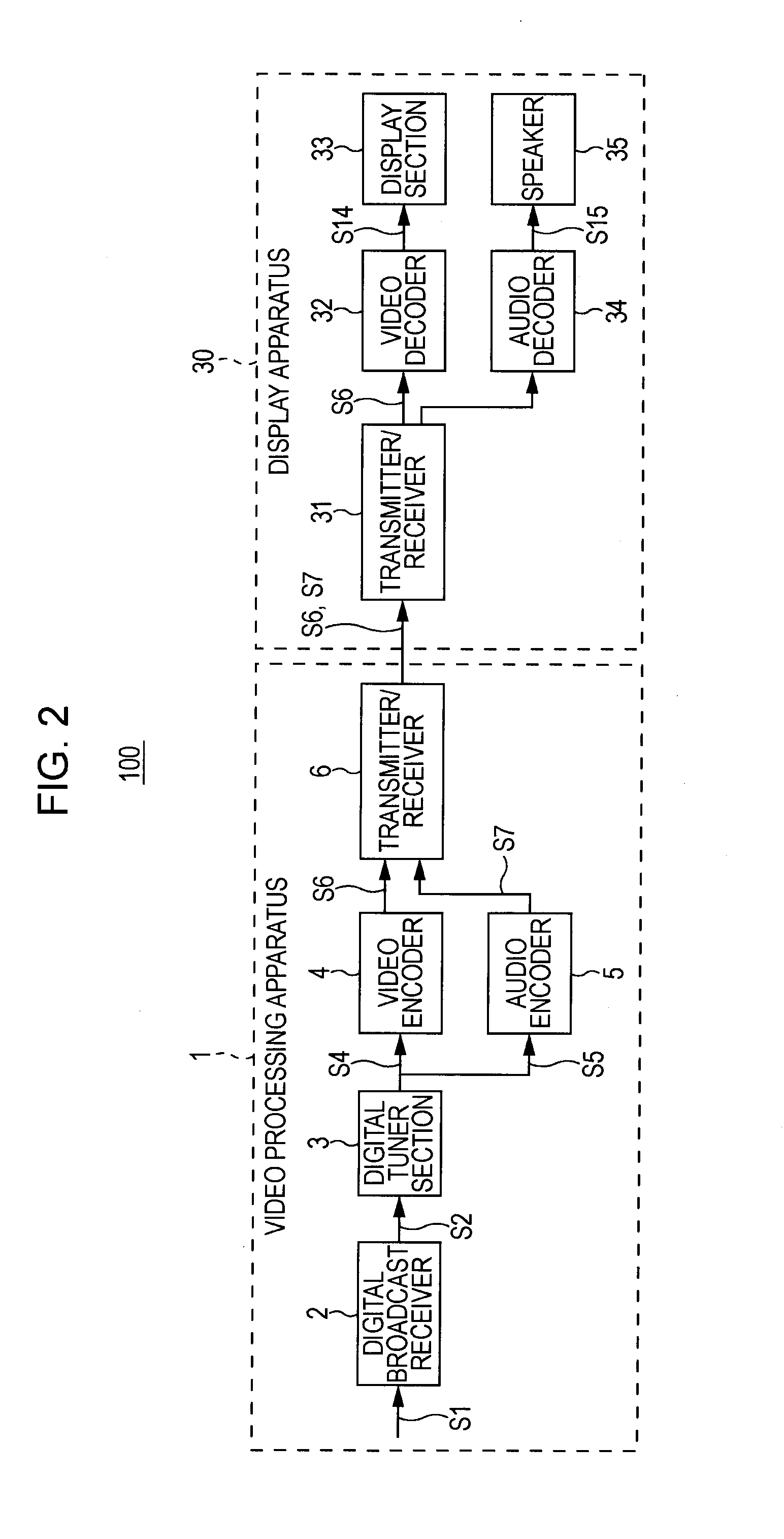
[0042]Reference numeral 100 in FIG. 2 generally indicates a video processing system typified by a wireless video-data transmission system. The video processing system 100 is, for example, a wall-mounted television that receives broadcast signals of terrestrial digital broadcast and so on, and has a video processing apparatus 1 and a display apparatus 30.

[0043]The video processing apparatus 1 receives broadcast signals S1 and encodes video data, obtained therefrom, in accordance with H.264 / AVC (Advanced Video Coding) to generate a bit stream S6. The video processing apparatus 1 wirelessly transmits the bit stream S6 and encoded audio data S7, resulting from encoding of audio data, to the display apparatus 30. The display apparatus 30 decodes the bit stream S6 and the encoded audio data S7 and outputs a resulting image. As a result, the display apparatus 30 allows a user to enjoy broadcast-program content based on the ter...


PUM


Abstract

A video transmitting apparatus includes: an error receiver that receives, from a video receiving apparatus for receiving a bit stream resulting from encoding of video data including pictures, error information indicating that an error is detected; an encoding-mode selector that selects a propagation-prevention encoding mode as an encoding mode when the error receiver receives the error information; and an encoder that encodes the video data in accordance with the selected encoding mode. In the propagation-prevention encoding mode, intra coding is executed on a forced intra block; a search range is set for a reference encoding unit so as not to include correspondent pixels from a boundary line serving as a boundary between the forced intra block and another block, the correspondent pixels corresponding to the number of adjacent pixels; and a restriction is set on deblocking-filter processing through a change in deblocking-filter setting information.

Description

BACKGROUND OF THE INVENTION[0001]1. Field of the Invention[0002]The present invention relates to a video transmitting apparatus, a video receiving apparatus, a video transmitting method, and a video receiving method, which are preferably applied to, for example, an encoding apparatus that encodes video data distributed through terrestrial digital broadcast.[0003]2. Description of the Related Art[0004]Wireless transmission technology for wirelessly transmitting HD (high definition) moving-image data to display apparatuses, such as wall-hanged televisions, placed at remote locations has been developed. Transmission systems used for the wireless transmission technology employ, for example, millimeter waves using a 60 GHz band, an IEEE (Institute of Electrical and Electronics Engineers) 802.11n (wireless LAN [local area network]) using a 5 GHz band, and a UWB (ultra wide band).[0005]In the wireless transmission technology, the HD moving-image data is encoded and compressed for transmiss...

Claims


Application Information

Patent Timeline
Patent Type & Authority Applications(United States)
IPC IPC(8): H04N7/64H04N7/32H04N19/50H03M7/36H04N19/107H04N19/117H04N19/134H04N19/176H04N19/503H04N19/593H04N19/61H04N19/625H04N19/70H04N19/86H04N19/89H04N19/91
CPCH04N19/176H04N19/61H04N19/86H04N19/166H04N19/89H04N19/107
Inventor TANAKA, JUNICHIYAGASAKI, YOICHIKITAMURA, TAKUYA
Owner SONY CORP
Why Eureka
Try Eureka