Fastening device having a retention element and method of manufacture

a technology of retention element and fastening device, which is applied in the direction of threaded fasteners, screws, bolts, etc., can solve the problems of non-reactive polyamide hot melt adhesive, tackiness, and unpleasant handling of non-reactive polyamide hot mel

Inactive Publication Date: 2008-11-27
ND IND INC
View PDF10 Cites 15 Cited by
  • Summary
  • Abstract
  • Description
  • Claims
  • Application Information

AI Technical Summary

Benefits of technology

[0012]The invention also relates to a method of forming a retention element in the interior of a first, female portion of a fastening device having a bore open at both ends adapted to receive a second, male portion. The preferred method comprises preheating the fastening device to a temperature above the melting point or flow point of the heat resistant polymer; applying a discrete shot of a retention element material comprising the heat resistant polymer onto an interior surface of the bore; heating the retention element material at least to the melting point or flow point of the heat resistant polymer to liquefy the retention el...

Problems solved by technology

The non-reactive polyamide hot melt adhesive, however, remains tacky to touch after being applied and solidified on collar, and becomes even tackier at high temperatures of about 100° F. or higher.
Thus, the non-reactive polyamide hot melt can be unpleasant to handle and can interfere with rivet tooling by gumming up the tool and physically upsetting the rivet installation at a temperature higher than 100° F. In addition, such non-reactive polyamide hot melts must be sto...

Method used


Image

  • Fastening device having a retention element and method of manufacture
  • Fastening device having a retention element and method of manufacture
  • Fastening device having a retention element and method of manufacture

Examples


example 1

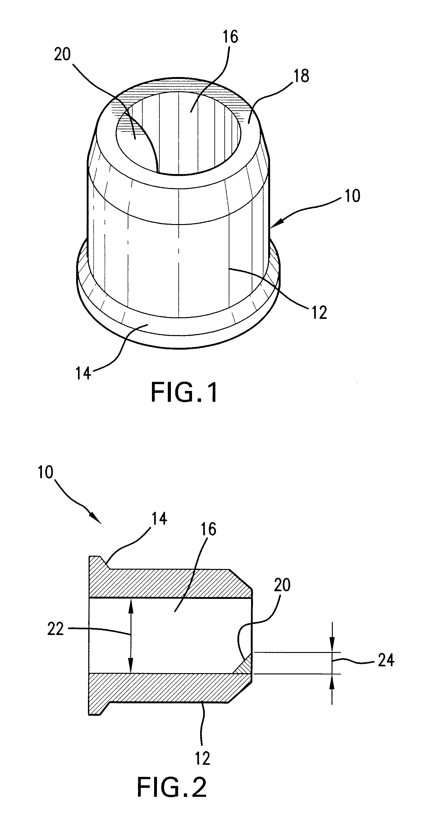
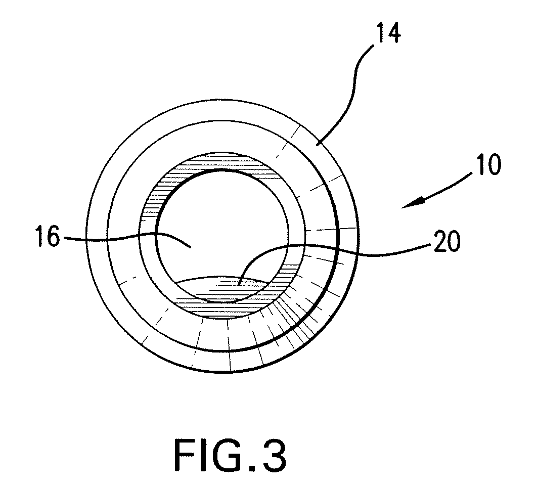
Preparation of a Collar with a Retention Element

[0056]Two types of retention element materials comprising ethylene acrylic acid copolymer as the base polymer were prepared and provided on flanged collars. One of the retention element materials was made with Corvel® as the base polymer. The other retention element material comprised a blend of 70% polyethylene and 30% polyethyl methacrylate, a diacrylic compound as an adhesion promoter, and azal amid dicarbon as a blowing agent.

[0057]The collars were carbon steel collars with zinc chromate finish manufactured by Huck Manufacturing Company, Irvine, Calif. The collars had a ⅝ inch diameter (with an inner diameter of about 0.650 to 0.665 inches and an outer diameter of about 0.970 to 1.010 inches) and a height of about 0.929 to 0.959 inches.

[0058]After preheating the collars to 400° F., the retention element materials were applied to the collars, with each collar receiving one of the two retention element materials. The retention elemen...

example 2

Tensile Strength of a Retention Element Made with Urethane Reactive Hot Melt

[0060]A retention element material comprising PUR-FECT LOK® 475A urethane reactive hot melt (manufacturer no. 91-475A) as the base polymer was prepared and applied on a flanged collar. The collar was a carbon steel collar with zinc chromate finish manufactured by Huck Manufacturing Company, Irvine, Calif. The collar had a ⅝ inch diameter (with an inner diameter of about 0.650 to 0.665 inches and an outer diameter of about 0.970 to 1.010 inches) and a height of about 0.929 to 0.959 inches. The retention element material was deposited as a liquid, at an angle against the axis of the collar, and was allowed to cure in the air.

[0061]The resulting retention element exhibited the following tensile strengths:


PUM


Abstract

A fastening device such as a rivet collar that includes a retention element is disclosed. The retention element enhances the retention of a fastener within the fastening device by frictionally engaging the fastener. The retention element comprises a heat resistant base polymer, such as a reactive hot melt, an ethylene acrylic acid copolymer, or a polyethylene polymer blend, that does not melt or become tacky even at high temperatures, and therefore has high stability even under extreme storage conditions. Also disclosed is a method of forming such retention element on a fastening device.

Description

CROSS-REFERENCE TO RELATED APPLICATIONS[0001]This application claims the benefit of U.S. Provisional Patent Application No. 60 / 939,268, filed May 21, 2007, the contents of which are incorporated herein by reference thereto.FIELD OF THE INVENTION[0002]The invention relates to a fastening device having a retention element that provides enhanced retention of a fastener within the device.BACKGROUND OF THE INVENTION[0003]Fastening systems with male and female components, such as a rivet fastening system, are well known. One type of traditional rivet fastening system includes a rivet pin and a collar. The rivet pin is inserted through holes in two panels being fastened, and the collar is placed over the pin. An installation tool pulls the pintail of the rivet pin while pushing on the collar to remove any gap between work surfaces. The tool then swages the collar into the locking grooves of the rivet, causing the collar to lengthen and develop clamp around the rivet. When swaging of the co...

Claims


Application Information

Patent Timeline
IPC IPC(8): F16B41/00F16B19/08
CPCF16B19/05F16B41/002
Inventor SNOW, GERALD F.STEMPIEN, CHARLES M.
Owner ND IND INC
Why Eureka
Try Eureka