

Try-in implant with angulated attachment portion
a technology of an attachment portion and a tryin implant, which is applied in the field of tryin implants, can solve the problems of difficult handling and no visual impression of the surgeon, and achieve the effect of maximum strength
- Summary
- Abstract
- Description
- Claims
- Application Information
AI Technical Summary
Benefits of technology
Problems solved by technology
Method used
Image

Examples
Embodiment Construction
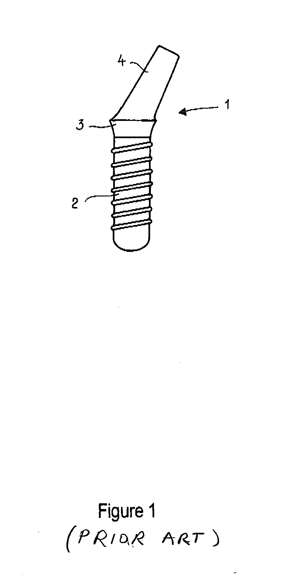
[0040]FIG. 1 shows one detailed description embodiment of a final implant in the form of an angulated one-part implant 1 according to the state of the art. It comprises an anchoring part 2 with a threaded section, a neck part 3 and a mounting part 4.
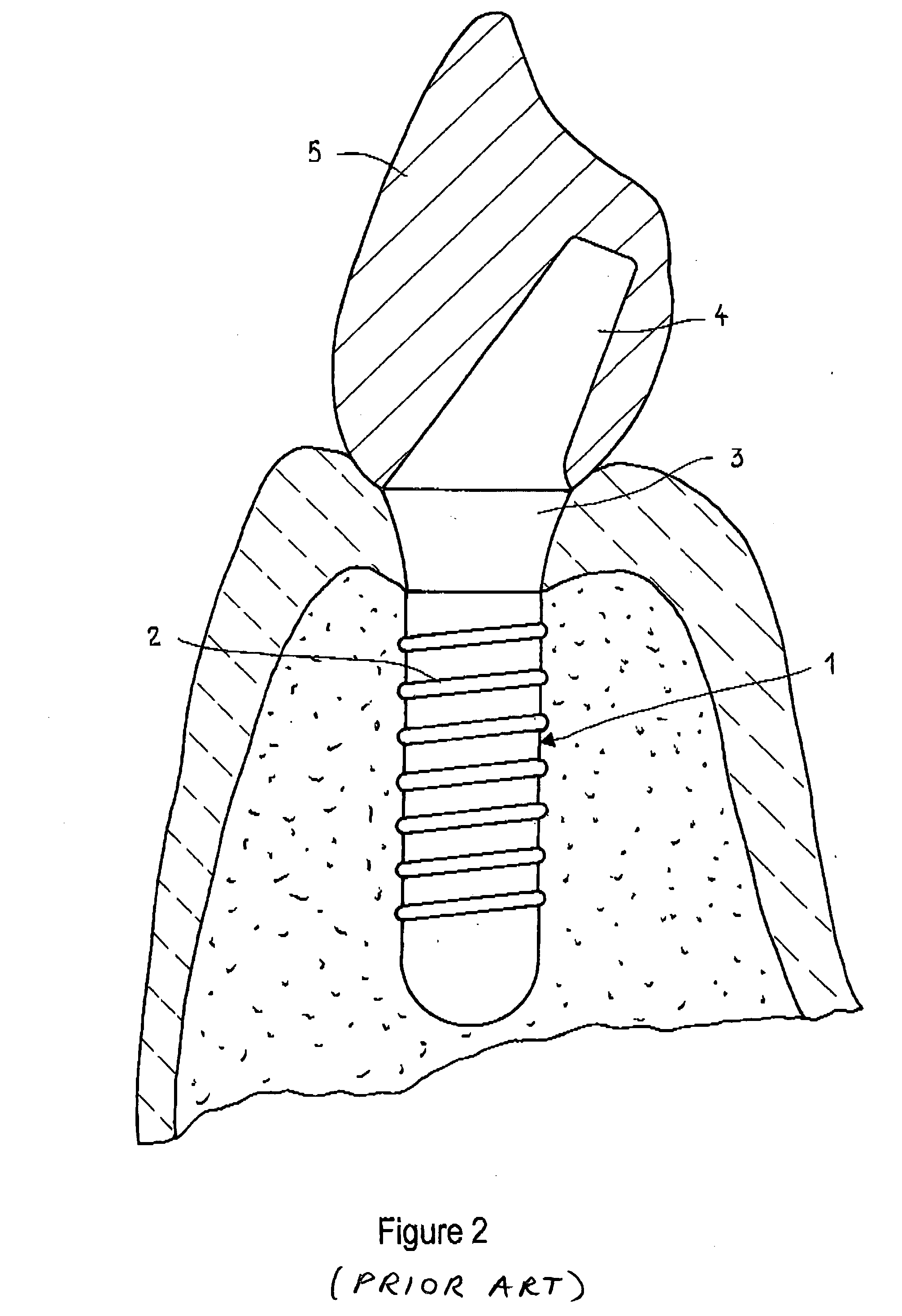
[0041]FIG. 2 shows an angulated final implant 1 with a mounted crown 5 according to the state of the art. It comprises an anchoring part 2 with a threaded section, a neck part 3 and a mounting part 4. On the mounting part 4, the crown 5 is attached.
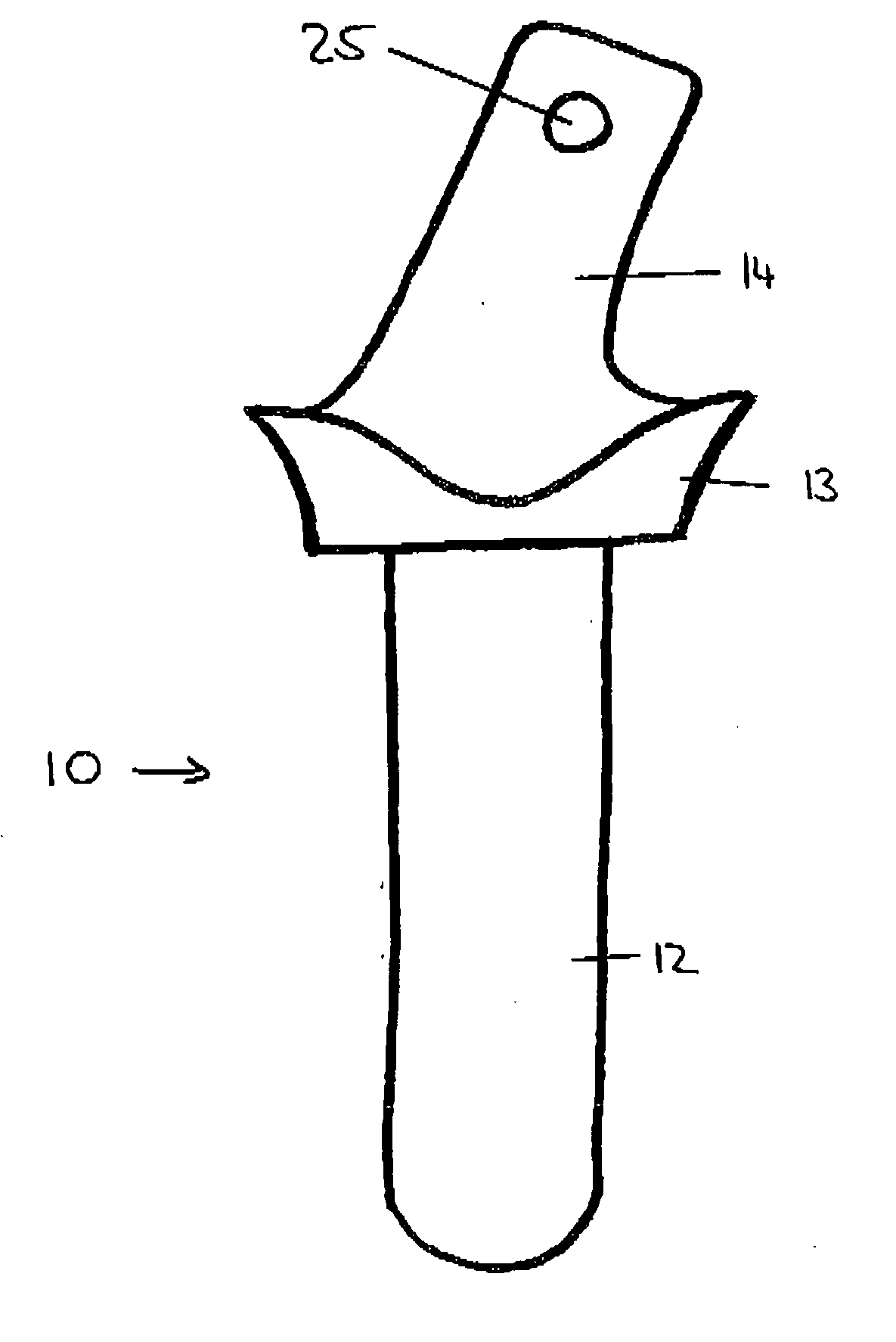
[0042]FIG. 3 shows a try-in implant 10 according to one embodiment of the present invention with an angulated attachment portion 14. The try-in implant 10 comprises a body portion 12 to be received in a pilot hole. The body portion 12 has a length of about 6 to 8 mm and corresponds to the drill hole and subsequently the anchoring part 2 of the final implant. At the upper end of the body portion 12, a neck portion 13 having a length of about 1 mm is formed, which may comprise a slightly enlarge...
PUM
 Abstract
Description
Claims
Application Information