Overpressure protection for an aircraft fuel tank system

a fuel tank system and overpressure protection technology, which is applied in the direction of plug valves, aeration devices, functional valve types, etc., can solve the problems of affecting the service life of the frangible disc,

Active Publication Date: 2008-12-04
AIRBUS OPERATIONS LTD
View PDF10 Cites 20 Cited by
  • Summary
  • Abstract
  • Description
  • Claims
  • Application Information

AI Technical Summary

Benefits of technology

[0018]By eliminating the need to remove all of the stack pipe unit from the venting tank, it may be possible to replace a frangible element in the stack pipe unit without needing to remove an access panel and / or without requiring fuel tank entry. This can enable the frangible element to be replaced relatively quickly and cheaply.
[0026]A seal between the frangible element and the stack pipe unit may thereby be formed reliably and quickly. The risk of the frangible element being damaged during fitting may also be reduced. Furthermore it may be possible to replace a frangible element in the stack pipe unit without requiring fuel tank entry. This may reduce aircraft downtime, cost and / or avoid dispatch delays.
[0029]By providing a spare frangible element in the venting tank structure, a replacement frangible element may be readily available in the event that a frangible element in the overpressure protector needs replacing. Thus, undesirable delays caused by a replacement frangible disc not being readily available may be reduced. This can enable the frangible element to be replaced relatively quickly and cheaply. This may also reduce the potential for fitting an incorrect replacement frangible disc as the spare unit can be carefully checked before being installed as a spare, rather than being replaced under severe time constraints following pre-dispatch checks.

Problems solved by technology

Replacing the frangible disc may therefore be relatively expensive and time consuming, and may result in a dispatch delay.
In addition, the frangible disc may be damaged by over-tightening the bolts attaching the lid of the stack pipe to the base, or tightening the bolts on one side of the lid earlier than those on another side of the lid.
For example, it can be unduly complex, vulnerable to jamming and / or unduly heavy.
Another problem that has been identified with certain forms of overpressure protection relates to the fact that specific type of frangible disc may need to be fitted for specific applications (for example the disc may need to be a particular size or have a particular pressure rating).
When a new frangible disc is to be fitted, significant delays can be caused if the replacement disc is not readily available (as may be the case if, for example, the aircraft has landed at a relatively remote airport, but is approaching the end of its permitted flight time for flying with a broken frangible disc).

Method used


Image

  • Overpressure protection for an aircraft fuel tank system
  • Overpressure protection for an aircraft fuel tank system
  • Overpressure protection for an aircraft fuel tank system

Examples


first embodiment

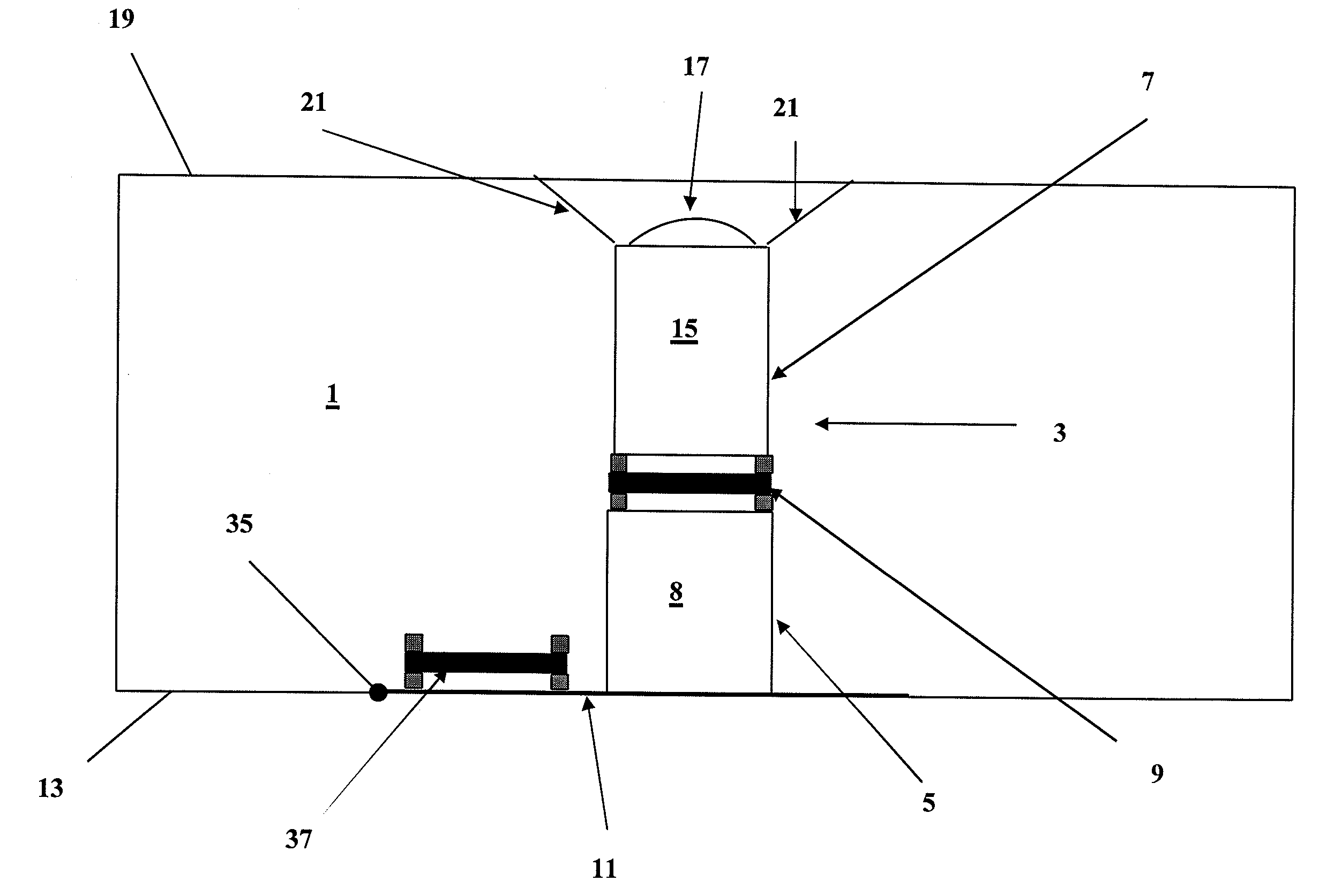
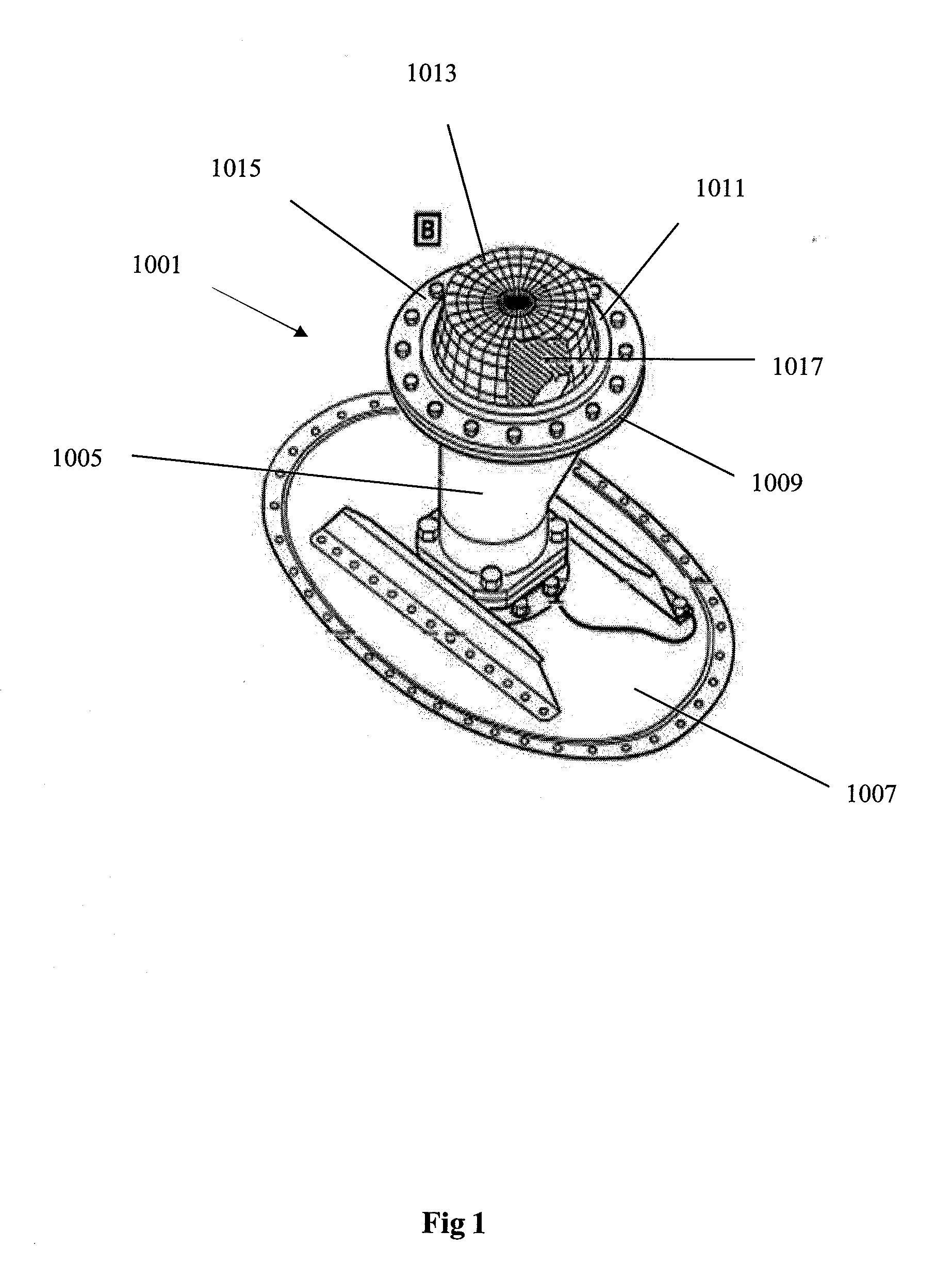
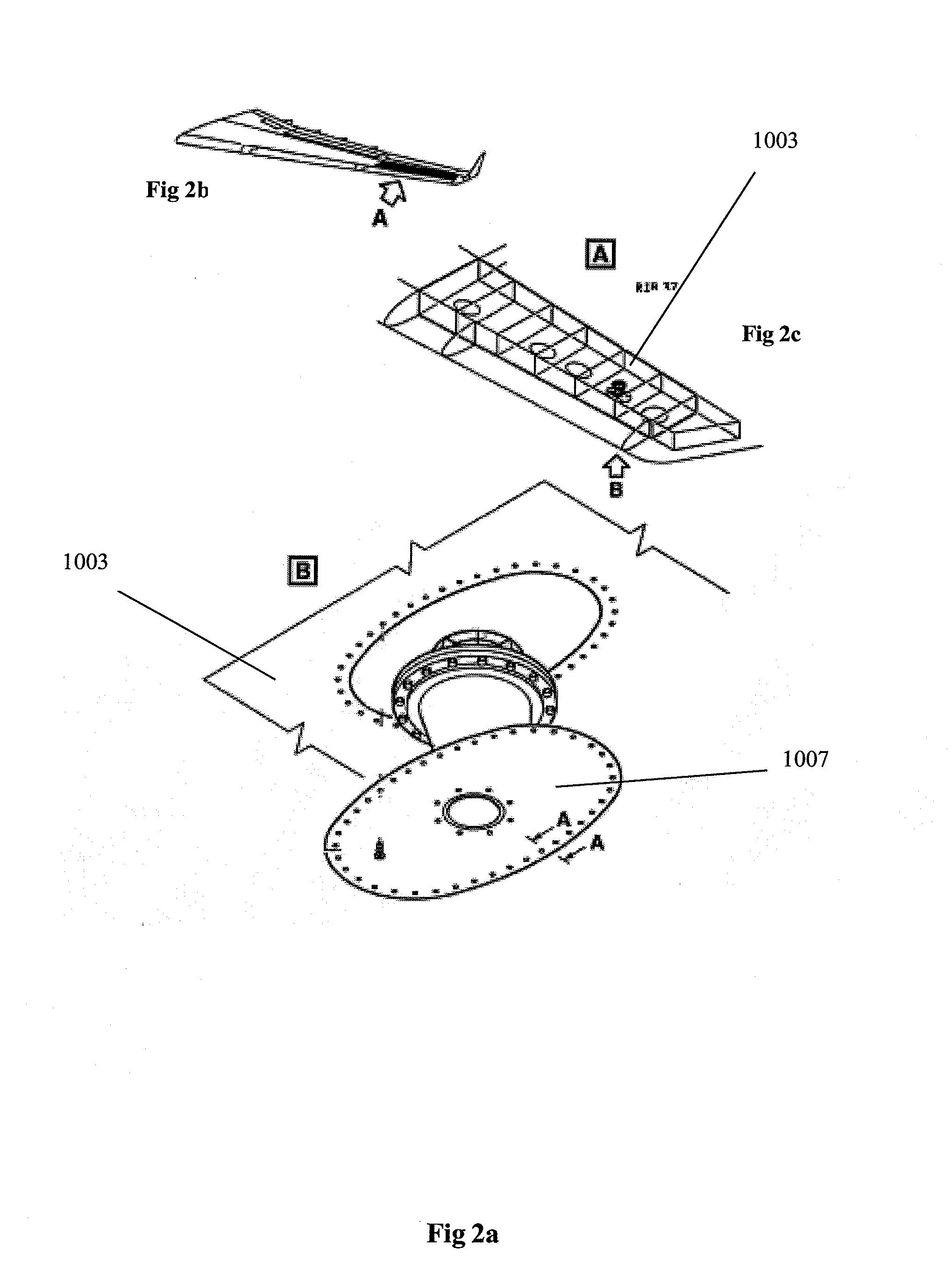
[0061]The stack pipe unit 103 is broadly similar to the first embodiment except for differences described below. Firstly, the lower portion 105 of the stack pipe unit 103 is not pivotably mounted on the lower surface 113 of the surge tank structure and is instead attachable by a series of fasteners 139 located around the edge of the panel 111 on the lower portion 105, which allows the lower portion 105 to be fully detached from the surge tank 101. The fasteners are in the form of bayonet-type fittings (the male part 139a of the fitting being located on the lower portion 105 of the surge tank structure and the female part 139b being located in the inner surface of the lower wall 113 of the surge tank 101). The panel 111 is generally circular rather than rectangular to aid the fitting of the lower stack pipe portion 105.

[0062]By pushing and twisting the lower portion to release the bayonet-fitting, the stack pipe unit 103 can be lowered from the fitted configuration (shown in FIG. 8) ...

second embodiment

[0064]In the invention the upper portion 107 of the stack pipe unit 103 is coupled to the surge tank by means of being integrally formed with the surge tank structure 101. Thus the upper portion remains coupled to the surge tank 101 in both the fitted and replacement configurations.

[0065]FIG. 10 shows a stack pipe unit 203 on a surge tank 201 according to a third embodiment of the invention. Features in the third embodiment of the invention that correspond to similar features in the first embodiment of the invention, are shown with the same reference numerals as in the first embodiment, but with the addition of the prefix ‘20’ (or ‘2’ where appropriate).

[0066]In the third embodiment, the stack pipe unit203 is similar to that of the second embodiment except that the surge tank 201 has been provided with three spare frangible disc holders: a first holder is positioned on the lower, inner, surface 213 of the surge tank 201 and remains in the surge tank 201 when the lower portion 205 of...


PUM

PropertyMeasurementUnit
pressureaaaaaaaaaa
pressureaaaaaaaaaa
pressureaaaaaaaaaa

Abstract

An aircraft venting tank (for example a surge tank) has a stack pipe unit. The stack pipe unit comprises first and second portions and houses a frangible overpressure protector element (for example a frangible disc). The stack pipe unit may be arranged to have a fitted configuration in which the first portion of the stack pipe unit is attached to a part of the venting tank structure, the first portion is coupled to the second portion, and the second portion is coupled to another part of the venting tank structure. The first portion may be held in a relationship with the second portion so as to form a seal between the frangible element, and the first and second portions. In a frangible element-replacement configuration the second portion may be coupled to the venting tank structure, such that the frangible overpressure protector element can be replaced without removal of the second portion from the venting tank structure. The venting tank may include a frangible element holder for holding a spare frangible element for use in an overpressure protector unit.

Description

TECHNICAL FIELD[0001]The present invention relates to overpressure protection for an aircraft fuel tank system. More particularly, but not exclusively, the invention relates to an aircraft venting tank structure having an overpressure protector unit associated therewith, and a method of operating an aircraft comprising such a structure.BACKGROUND OF THE INVENTION[0002]It is desirable in an aircraft fuel tank system, to have an overpressure protector to relieve excess pressure and prevent the pressure from reaching a dangerous level.[0003]In a fuel tank system, large pressure differentials may occur when, for example: the aircraft is being refuelled (resulting in high pressure in the tank relative to the atmosphere i.e. positive pressure differential); or the aircraft is making an emergency descent (resulting in low pressure in the tank relative to the atmosphere i.e. negative pressure differential). A common type of overpressure protector comprises a frangible disc, the frangible di...

Claims


Application Information

Patent Timeline
Patent Type & Authority Applications(United States)
IPC IPC(8): F16K24/04F16K17/40B23P19/00B21D39/00
CPCB64D37/005Y10T29/49826Y10T29/49815F16K17/16Y10T137/1714Y10T137/86324Y10T137/8811
Inventor SANDIFORD, J. PATRICKSMILES, MARK
Owner AIRBUS OPERATIONS LTD
Why Eureka
Try Eureka