
Micromechanical component having thin-layer encapsulation and production method

a technology of thin-layer encapsulation and micromechanical components, applied in the direction of semiconductor devices, semiconductor/solid-state device details, electrical devices, etc., can solve problems such as inability to easily implement processes

Inactive Publication Date: 2008-12-04
ROBERT BOSCH GMBH
View PDF3 Cites 8 Cited by
  • Summary
  • Abstract
  • Description
  • Claims
  • Application Information

AI Technical Summary

Benefits of technology

[0008]One advantageous embodiment of the micromechanical component provides that the thin layer is a deflectable diaphragm. In that way, a pressure sensor may advantageously be created whose working range may be adjusted by the internal pressure of the gas phase.

Problems solved by technology

This is not implemented easily using the processes involving a thin- layer cap.

Method used


Image

  • Micromechanical component having thin-layer encapsulation and production method
  • Micromechanical component having thin-layer encapsulation and production method
  • Micromechanical component having thin-layer encapsulation and production method

Examples


Embodiment Construction

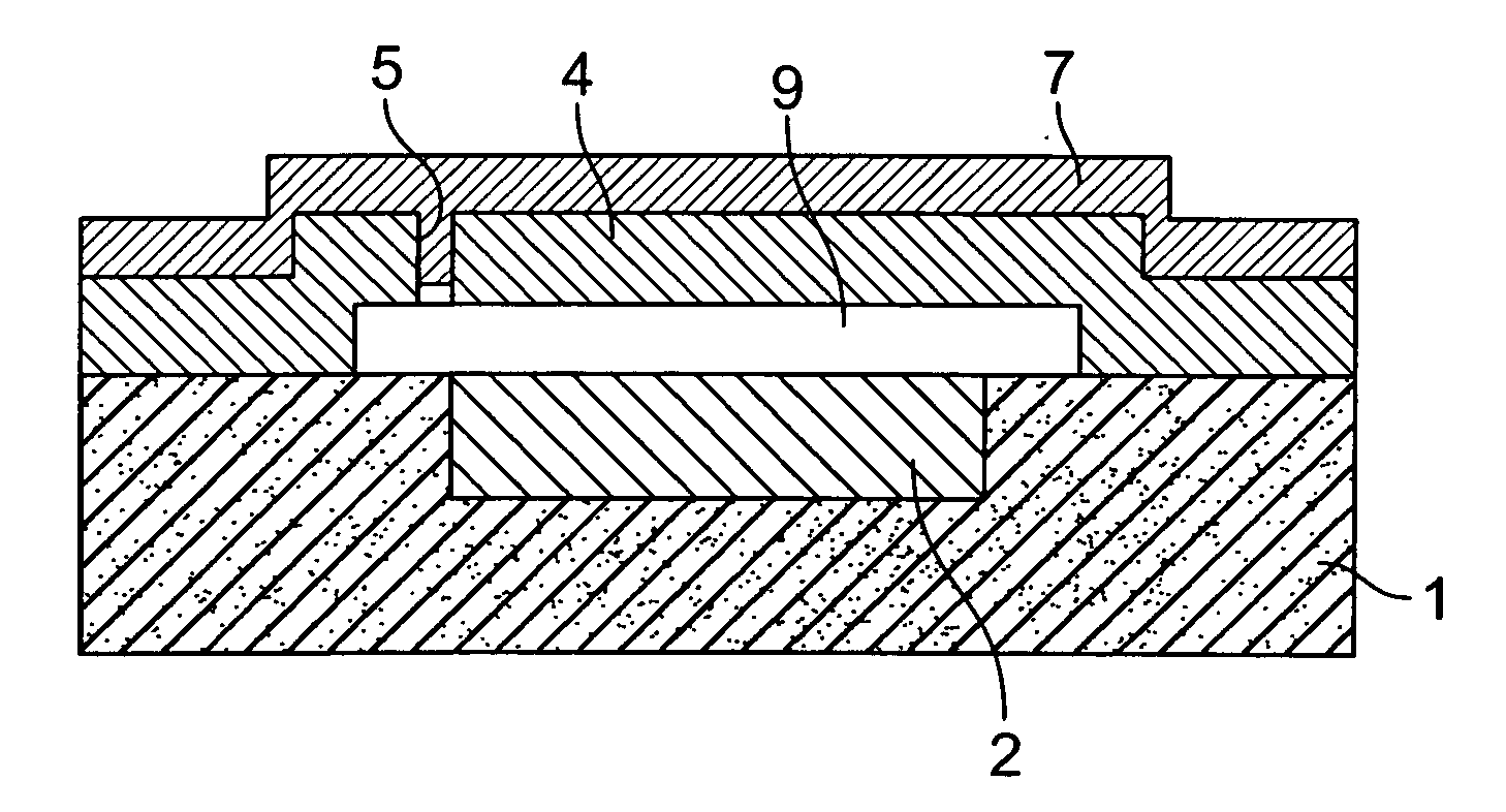
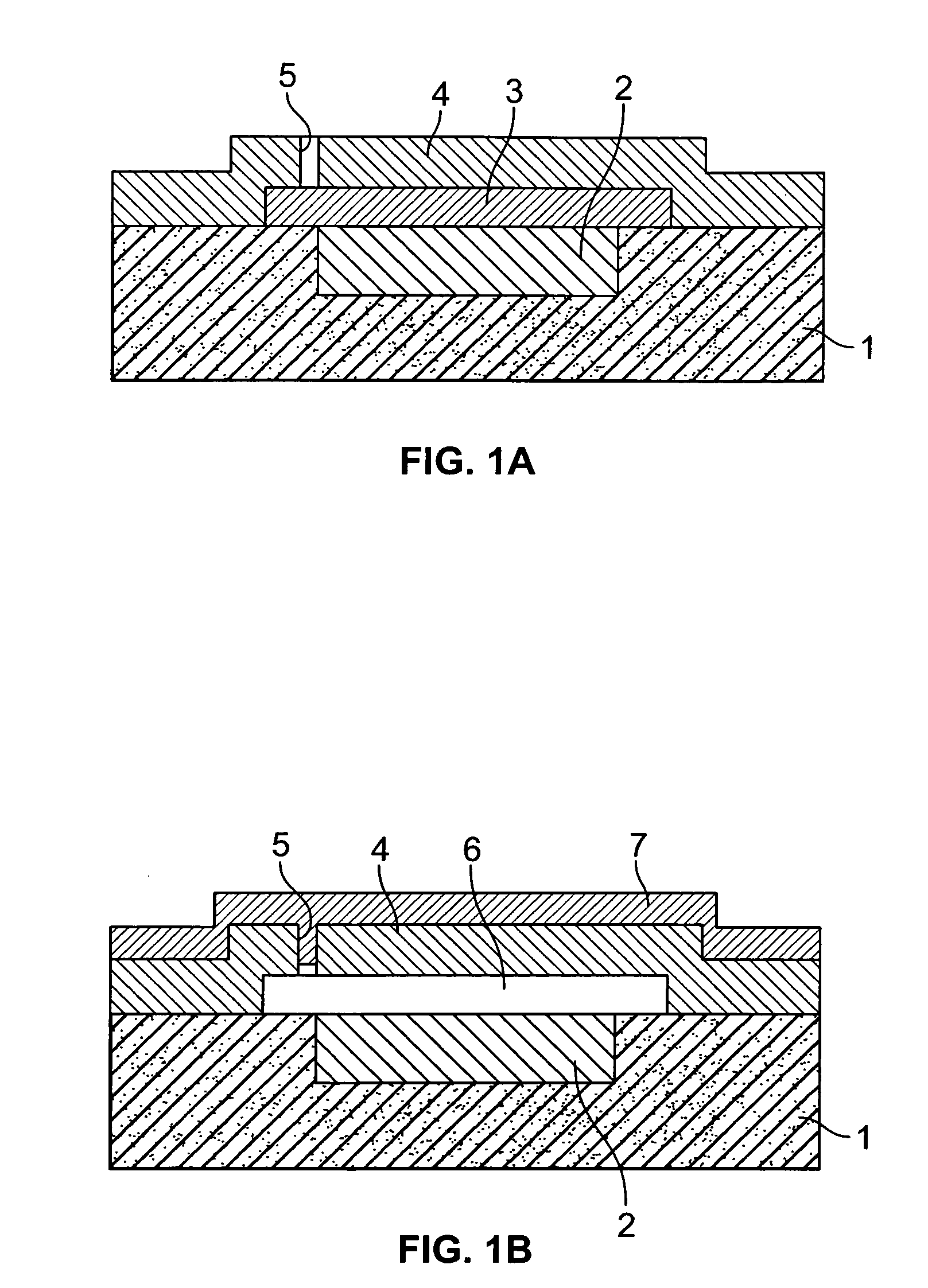
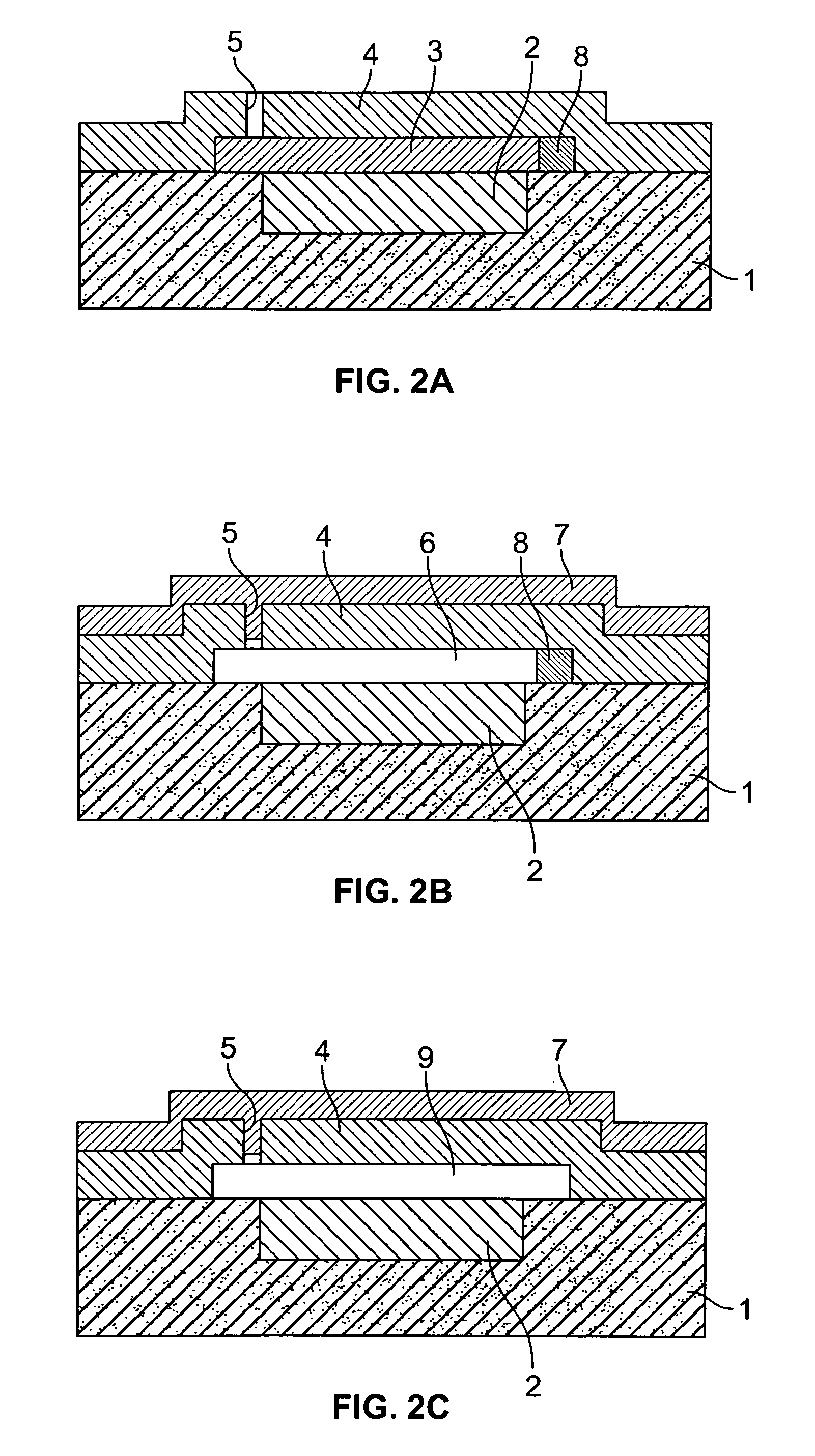
[0014]FIGS. 1a and 1b show schematically a sensor encapsulated using a thin layer, according to the related art. FIG. 1a shows a substrate 1 having a recess into which a sensor structure 2 has been inserted. Above this, there is a sacrificial layer 3, which defines the distance of sensor structure 2 from a thin-layer encapsulation 4. In thin-layer encapsulation 4, openings 5 have been inserted through which sacrificial layer 3 may be etched. In FIG. 1b this sacrificial layer 3 has been etched away, and using a closing layer 7, the etching accesses in the form of openings 5 have been sealed. In addition, in cavity 6, a gas phase is enclosed having the process pressure, which was applied in response to the deposition of closing layer 7. This gas phase typically contains Ar or also N2 as important components. The process pressure typically amounts to a few 10 mbar. This process pressure represents the operating pressure of the sensor and, at the same time, influences its properties, am...


PUM


Abstract

A micromechanical component having a substrate and having a thin-layer, as well as having a cavity which is bounded by the substrate and the thin-layer, at least one gas having an internal pressure being enclosed in the cavity. The gas phase has a non-atmospheric composition. A method for producing a micromechanical component having a substrate and having a thin-layer encapsulation, as well as having a cavity which is bounded by the substrate and the thin-layer encapsulation. The method has the steps of positioning a polymer in a cavity, closing the cavity and generating a gas phase of non-atmospheric composition in the cavity by decomposing at least a part of the polymer. An internal pressure is generated, which may be higher than the process pressure when the cavity is closed.

Description

FIELD OF THE INVENTION[0001]The present invention relates to a micromechanical component having a substrate and having a thin-layer encapsulation, as well as having a cavity which is bounded by the substrate and the thin-layer encapsulation, at least one gas having an internal pressure being enclosed in the cavity.BACKGROUND INFORMATION[0002]For sensors encapsulated by a thin layer, because of the production process, the process pressure of the enclosing process (as a rule, a few mbar) is enclosed. The method of seal glass encapsulation makes possible a pressure enclosure by the atmosphere used in the encapsulation.[0003]Many sensors, such as acceleration sensors, require a high enclosed pressure for their operation. This is not implemented easily using the processes involving a thin- layer cap.[0004]It is described in European Patent No. EP 04 101 108 that, in addition to the process gas, one may also enclose an additional inert gas in a sensor encapsulated using a thin layer.SUMMA...

Claims


Application Information

Patent Timeline
IPC IPC(8): H01L21/56H01L23/02
CPCB81C1/00293B81C2203/0136B81C2203/0145
Inventor FEYH, ANDO
Owner ROBERT BOSCH GMBH
Learn More