Conditioning Device For Plastic Items And Process

a technology of conditioned devices and plastic items, which is applied in the direction of dough shaping, application, manufacturing tools, etc., can solve the problems of limiting the productivity difficult to shorten the duration of this stage, and direct affecting the effect of the container production plant, so as to achieve high productivity, and ensure the effect of quality

Active Publication Date: 2008-12-04
SIPA SOCIETA INDUSTRIALIZZAZIONE PROGETTAZIONE E AUTOMAZIONE SPA
View PDF25 Cites 10 Cited by
  • Summary
  • Abstract
  • Description
  • Claims
  • Application Information

AI Technical Summary

Benefits of technology

[0012]It is an object of this invention to provide a device for conditioning plastic items, such as preforms or containers, that resolves the aforementioned problems. Said device will be straightforward and reliable to use, will help the injection moulding plant achieve high productivity levels, and will be cost effective to make, control, and maintain.
[0013]It is another object of this invention to provide a simple-to-implement process for conditioning plastic items, such as preforms or containers, suitable for high-capacity bottle making lines.

Problems solved by technology

This stage, which directly affects and limits the productivity of the container production plant, is the so-called “bottleneck” of the production line and lasts longer than the other stages carried out by the plant.
Furthermore, it is very difficult to shorten the duration of this stage; thus, improvements to the process have focused on shortening the cooling time inside the mould as much as possible and completing a significant part of the cooling after ejecting the preforms from the mould.
Unfortunately, said plant is somewhat complex to make and control.
Furthermore, it requires a large number of components that make it expensive to construct and maintain.

Method used


Image

  • Conditioning Device For Plastic Items And Process
  • Conditioning Device For Plastic Items And Process
  • Conditioning Device For Plastic Items And Process

Examples


Embodiment Construction

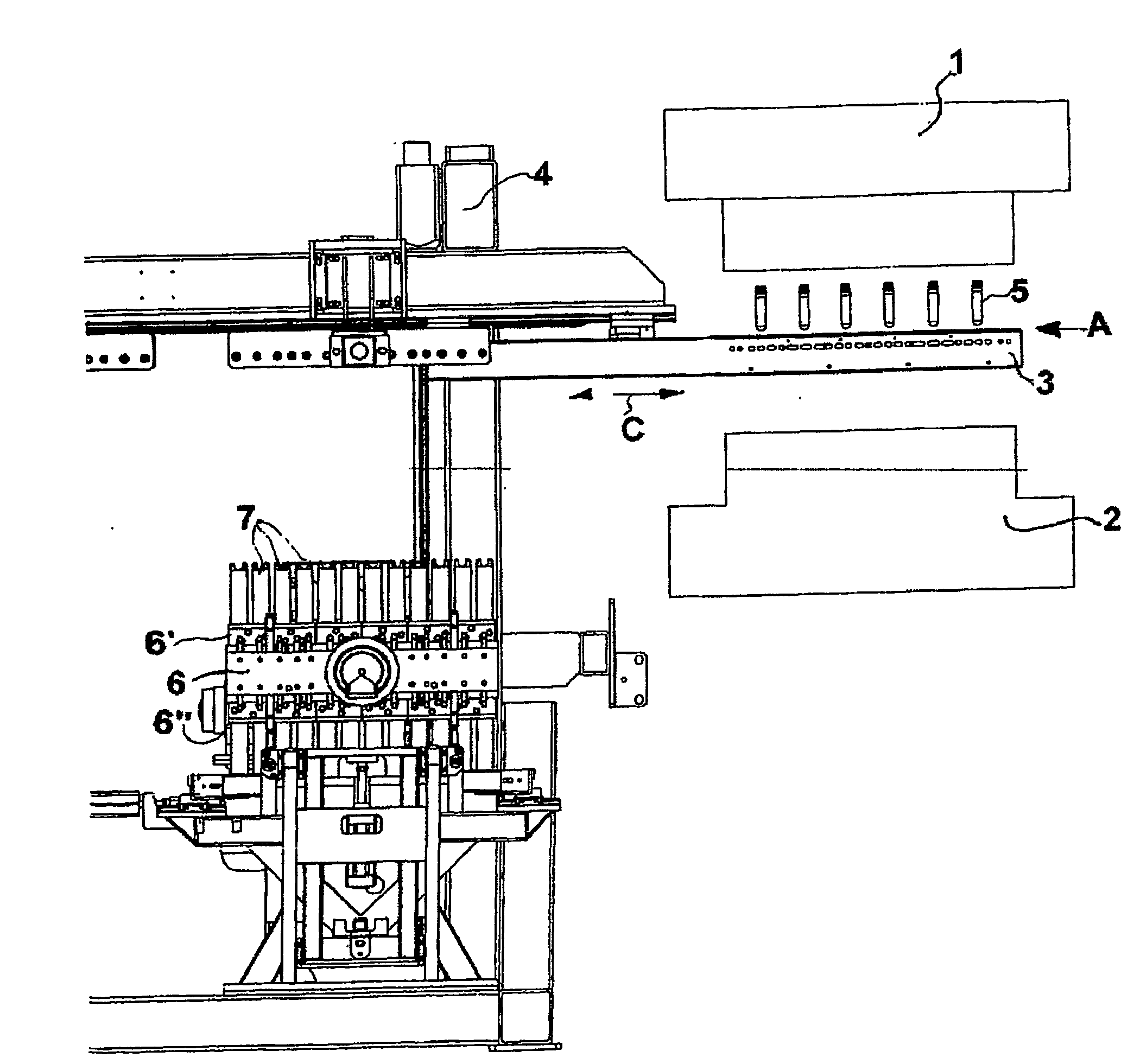
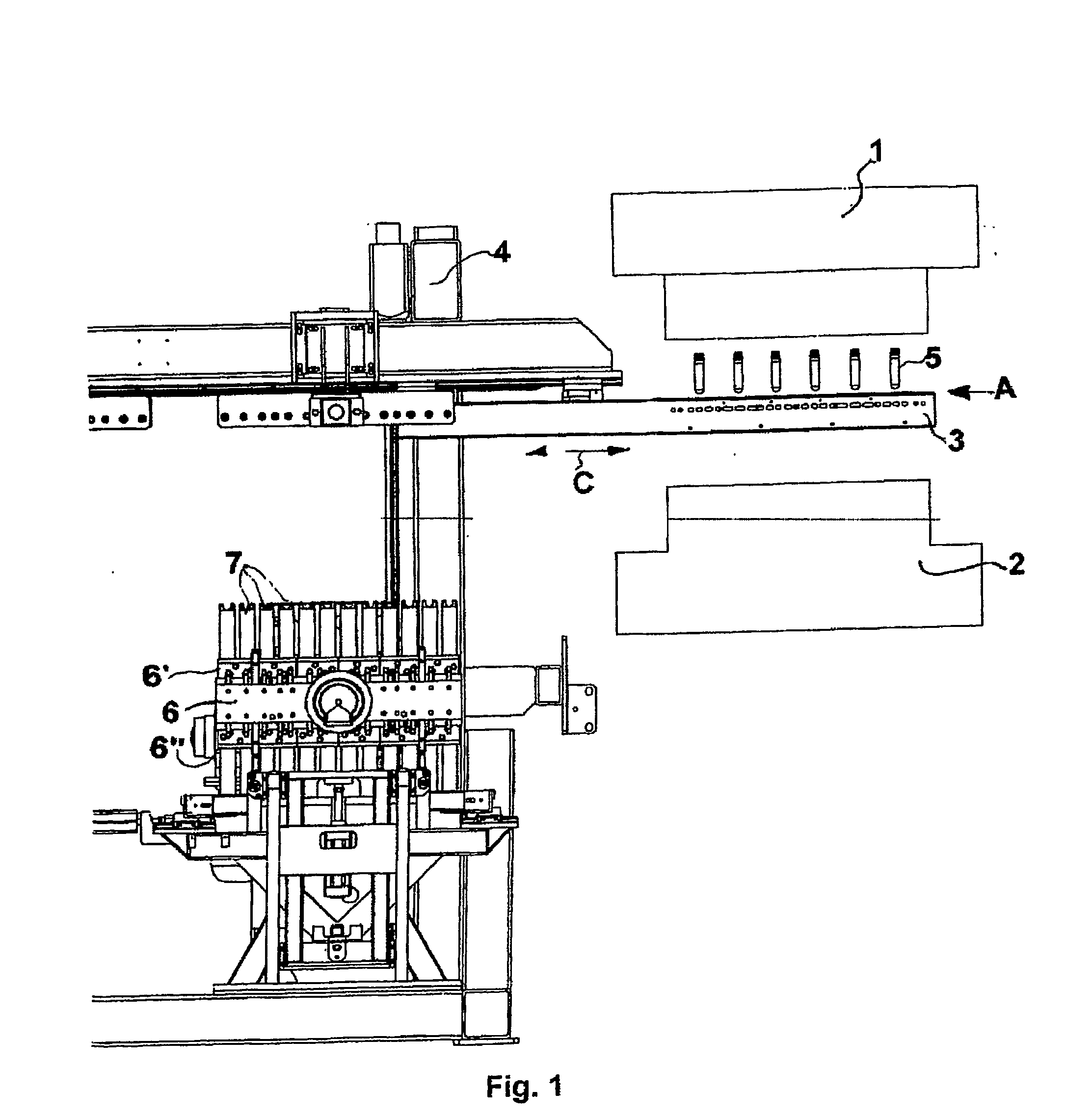
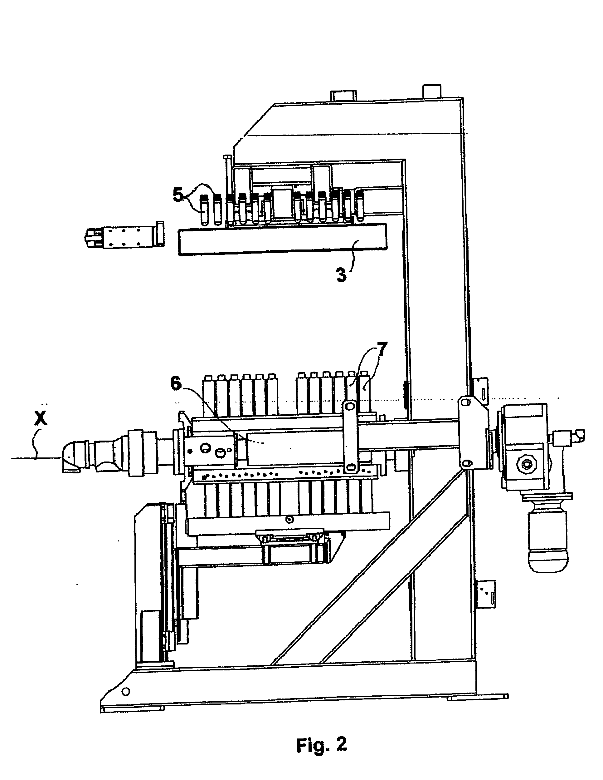
[0048]The Figures show the device in accordance with this invention for moulding and conditioning preforms. Said device comprises an injection mould of the known split mould kind—having two mould halves 1, 2 that open and close—operated by a press; when this mould is in the closed moulding position, it forms many injection mould cavities, which are not shown in detail in the Figures where the preforms are formed. The device includes a bearing structure 4 that supports a part for collecting, holding, and transferring the preforms, namely an arm 3. This arm can move in the direction of the arrow “C” and can move into the space vacated by the two open mould halves 1, 2 at the end of an injection moulding cycle. The arm 3 is able to house the preforms 5 that are released in a known manner—through a guillotine mechanism not shown in detail in the Figures—by the top mould 1. As was already mentioned, this operation takes place when the arm 3 moves into the space left when the split mould ...


PUM

PropertyMeasurementUnit
thicknessaaaaaaaaaa
heightaaaaaaaaaa
axis of rotationaaaaaaaaaa

Abstract

A device and process for conditioning plastic preforms (5) comprising a cooling turret (6) featuring faces fitted with many holders (7) for conditioning preforms (5). This turret rotates around a horizontal axis (X) and carries out a vertical traverse between a top position under an arm (3), which unloads the preforms from the mould, and a bottom position near the table for extracting the preforms (5) from the turret (6). Tie structure of the turret consists of two parallel bars (18, 19) and several joining plates (14) to which the bases of the holders (7) are attached.

Description

TECHNICAL FIELD[0001]This invention relates to a device for thermally conditioning plastic items. More particularly, it relates to a device for use in injection moulding plants producing many plastic items simultaneously, such as “preforms” (i.e. preform moulds, blanks, unfinished parts / products, workpieces), that are used later in blow moulding plants to make containers, especially plastic bottles or pots. This invention also relates to the corresponding conditioning process.BACKGROUND ART[0002]Plastic materials, such as PET (polyethylene terephthalate), have been used for some time now to make containers. This is particularly true for food-containing containers, especially drinks. Although said containers can be of different types, they shall be referred to hereinafter generically as bottles, which happen to be the most popular kind.[0003]Two main production processes are used to make plastic bottles; both processes involve making an intermediary product, the so-called “preform”. ...

Claims


Application Information

Patent Timeline
Patent Type & Authority Applications(United States)
IPC IPC(8): B29C45/72B29C49/64B29C35/16B29C45/42B29C49/06
CPCB29C45/4225B29C45/7207B29C49/06B29C2035/1616B29C2045/7214B29K2067/00B29K2105/253B29K2105/258B29L2031/7158B29C49/42077B29C2949/0715B29C2049/023B29C49/6427
Inventor ZOPPAS, MATTEOCORAN, MASSIMOPAVANETTO, JADER
Owner SIPA SOCIETA INDUSTRIALIZZAZIONE PROGETTAZIONE E AUTOMAZIONE SPA
Why Eureka
Try Eureka