
Wind Power Generation System and Method of Controlling Power Converter

a power generation system and wind power technology, applied in the direction of electric generator control, dynamo-electric converter control, machines/engines, etc., can solve the problem that the reactive current cannot be supplied to the electric power system

Inactive Publication Date: 2008-12-04
HITACHI LTD
View PDF6 Cites 57 Cited by
  • Summary
  • Abstract
  • Description
  • Claims
  • Application Information

AI Technical Summary

Benefits of technology

The patent text describes a wind power generation system that can supply a reactive current to an electric power system when there is a fault in the system. This is important because it helps to stabilize the power of the system. The system uses a doubly-fed generator and a power converter that can detect a decrease in stator current when there is a fault and reactivate the converter to output the reactive current. Overall, the invention provides a wind power generation system that can supply a reactive current to an electric power system when there is a fault.

Problems solved by technology

In the control method, there has been the problem that a reactive current cannot be supplied to an electric power system while the system is faulty.

Method used


Image

  • Wind Power Generation System and Method of Controlling Power Converter
  • Wind Power Generation System and Method of Controlling Power Converter
  • Wind Power Generation System and Method of Controlling Power Converter

Examples


embodiment 1

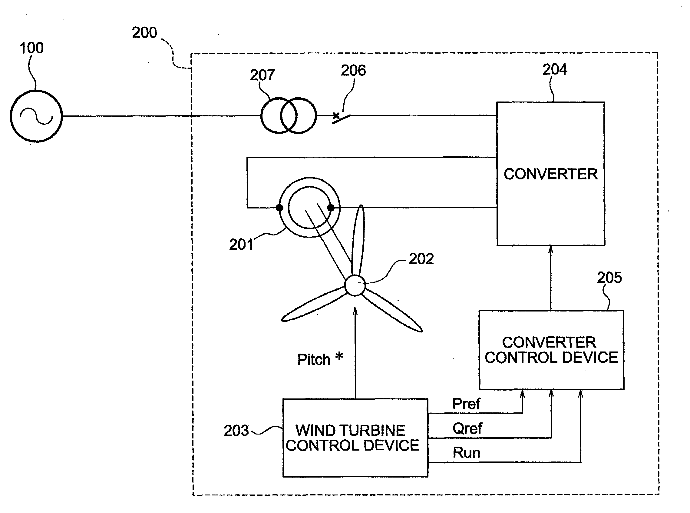
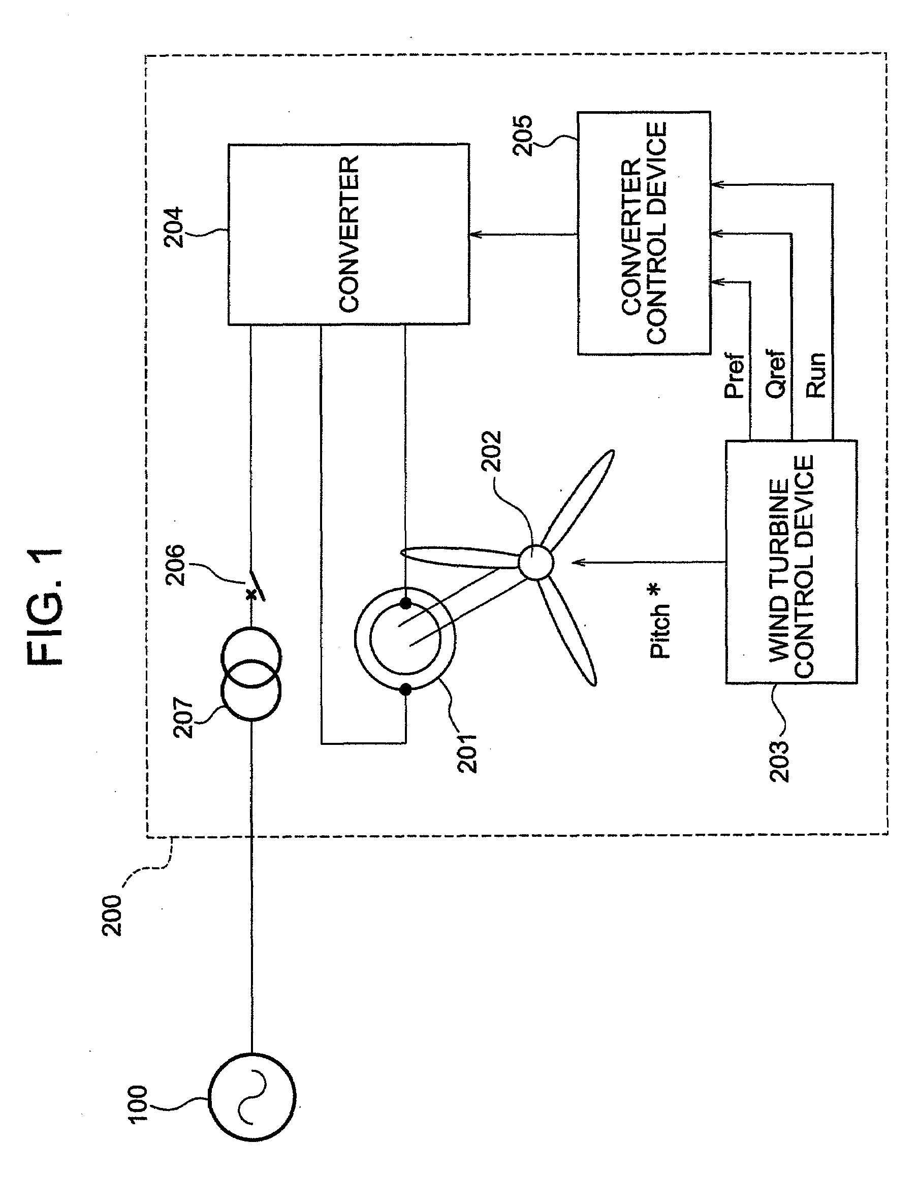
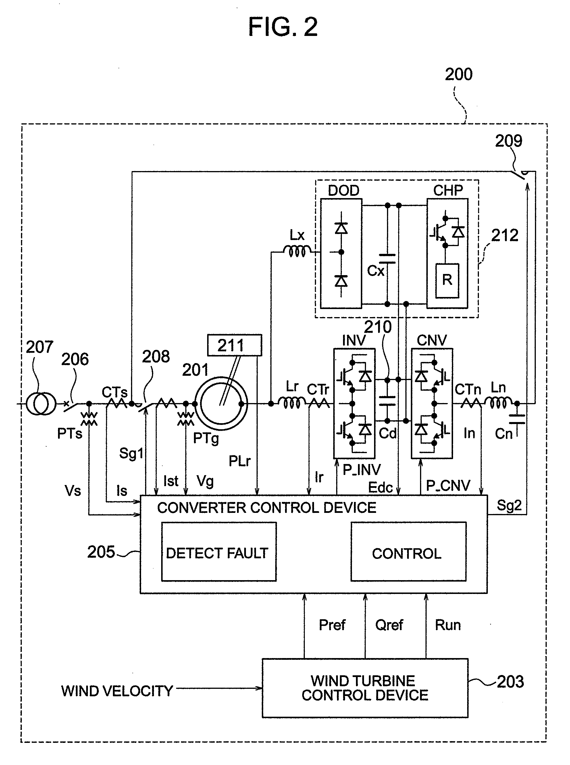
[0027]The device configuration (single-line diagram) of the first embodiment of the present invention is described below with reference to FIGS. 1 and 2. A wind power generation system 200 is connected to an electric power system 100 through a transmission line.

[0028]The wind power generation system 200 is mainly configured by a generator 201, a wind turbine 202, a wind turbine control device 203, a converter (excitation device) 204, and a converter control device 205.

[0029]The wind turbine 202 is mechanically connected to a rotor of the generator 201 (through a gear etc.). The rotor coil of the generator 201 is electrically connected to the converter 204, and the stator of the generator 201 is electrically connected to the electric power system through the breaker 206 and the transformer 207 etc.

[0030]The wind turbine control device 203 detects a wind velocity, controls the pitch angle of the wind turbine 202, calculates an active power command value, outputs an active power comman...


PUM


Abstract

A wind power generation system temporarily stops a power converter when a system disturbance occurs, and reactivates the power converter after detecting a solution of the problem of an influence (overcurrent of a stator, direct current component of a stator, overcurrent of a rotor, etc.) of a fault occurring in a doubly-fed generator during a system fault. During a system fault, a reactive current can be safely output from a doubly-fed generator to an electric power system without destroying equipment of the wind power generation system.

Description

CROSS-REFERENCE TO RELATED APPLICATION[0001]The present application relates to subject matters described in a co-pending patent application Ser. No. 11 / 769,753 filed on Jun. 28, 2007 entitled “VARIABLE SPEED WIND POWER GENERATION SYSTEM”, Ser. No. 11 / 751,742 filed on May 22, 2007 entitled “WIND POWER GENERATION APPARATUS, WIND POWER GENERATION SYSTEM AND POWER SYSTEM CONTROL APPARATUS”, Ser. No. 11 / 954,453 filed on Dec. 12, 2007 entitled “WIND POWER GENERATION SYSTEM”, and Ser. No. 12 / 116,272 filed on May 7, 2008 entitled “WIND POWER GENERATION SYSTEM AND OPERATING METHOD THEREOF” every which by Masaya Ichinose, et al. and assigned to the assignees of the present application. The disclosures of these co-pending applications are incorporated herein by reference.BACKGROUND OF THE INVENTION[0002]The present invention relates to a power generation system for providing power to an electric power system, and more specifically to a wind power generation system.[0003]The doubly-fed generato...

Claims


Application Information

Patent Timeline
Patent Type & Authority Applications(United States)
IPC IPC(8): H02P9/10H02P9/04
CPCF03D9/003H02P9/10H02P2101/15Y02E10/725H02P29/021F03D9/255F03D17/00H02P29/0241Y02E10/72
Inventor ICHINOSE, MASAYAOOHARA, SHINYAFUTAMI, MOTOOMATSUTAKE, MITSUGUSAKAI, HIROMITSU
Owner HITACHI LTD
Learn More