3-d robotic vision and vision control system

a robotic vision and control system technology, applied in the field of robotics and electronic displays, can solve the problems of cumbersome remote control of a robot, slow and clumsy, and operator's control of the robot is somewhat less intuitive, and the effect of reducing the number of operators

Inactive Publication Date: 2008-12-04
BARBER FRED +1
View PDF5 Cites 27 Cited by
  • Summary
  • Abstract
  • Description
  • Claims
  • Application Information

AI Technical Summary

Benefits of technology

[0008]The present invention relates to a system and method for remote robotic vision and vision control comprising a stereoscopic video camera mounted to a robot, and a remotely located stereoscopic display system. The stereoscopic imagery captured by the stereoscopic camera is transmitted via a wired or, alternatively, wireless communication link, to the stereoscopic display system, thereby allowing the operator of the robot to perceive depth and distance to objects in a manner that allows the operator to more precisely maneuver or otherwise use the robot.

Problems solved by technology

Unfortunately, the remote control of a robot can be cumbersome, slow and clumsy.
The technology interface between the operator and the robot tends to make the operator's control of the robot somewhat less intuitive, clumsier, slower, and more indirect than the operator is normally accustomed to experience in interacting physically with objects.

Method used


Image

  • 3-d robotic vision and vision control system
  • 3-d robotic vision and vision control system
  • 3-d robotic vision and vision control system

Examples


Embodiment Construction

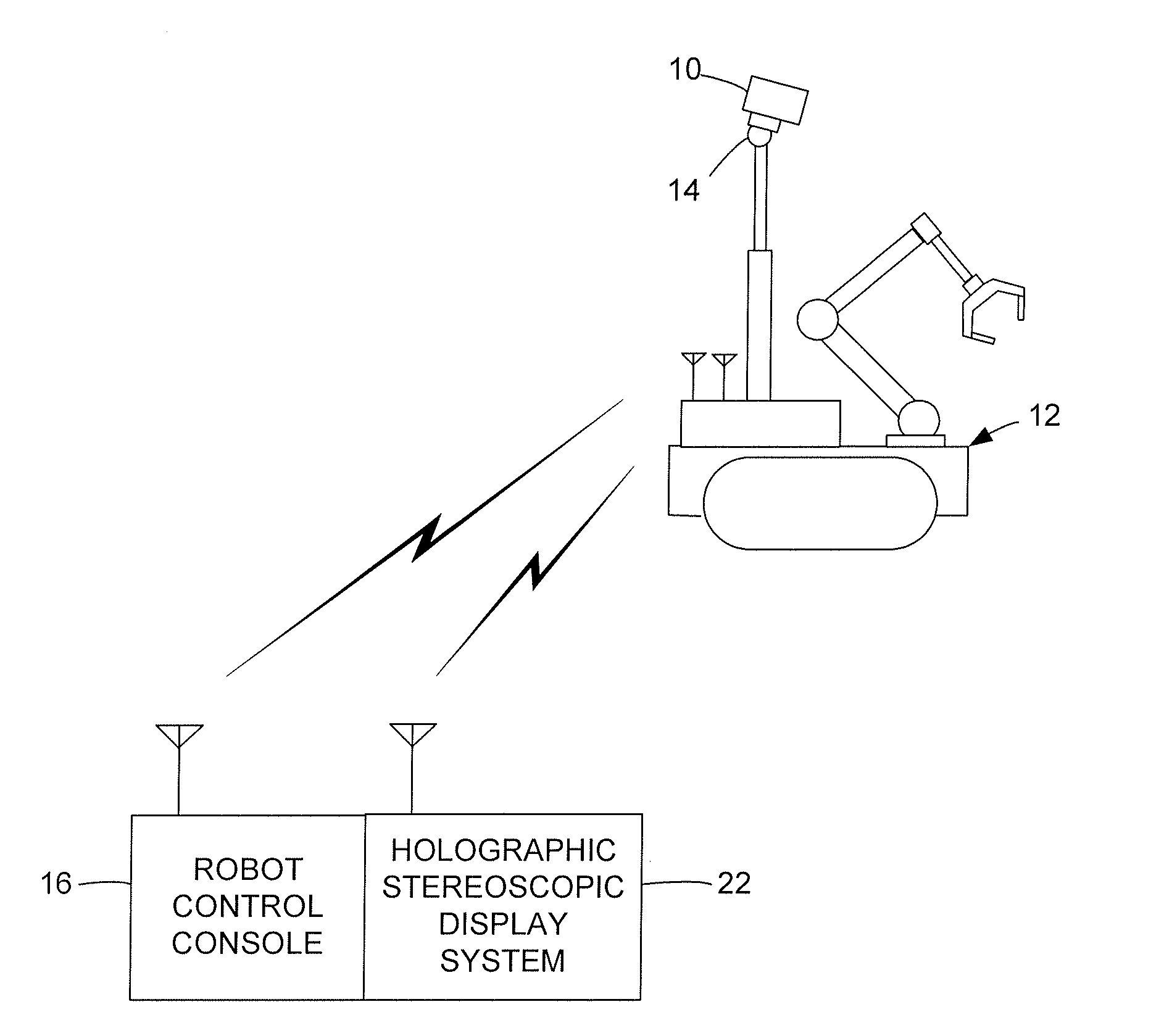
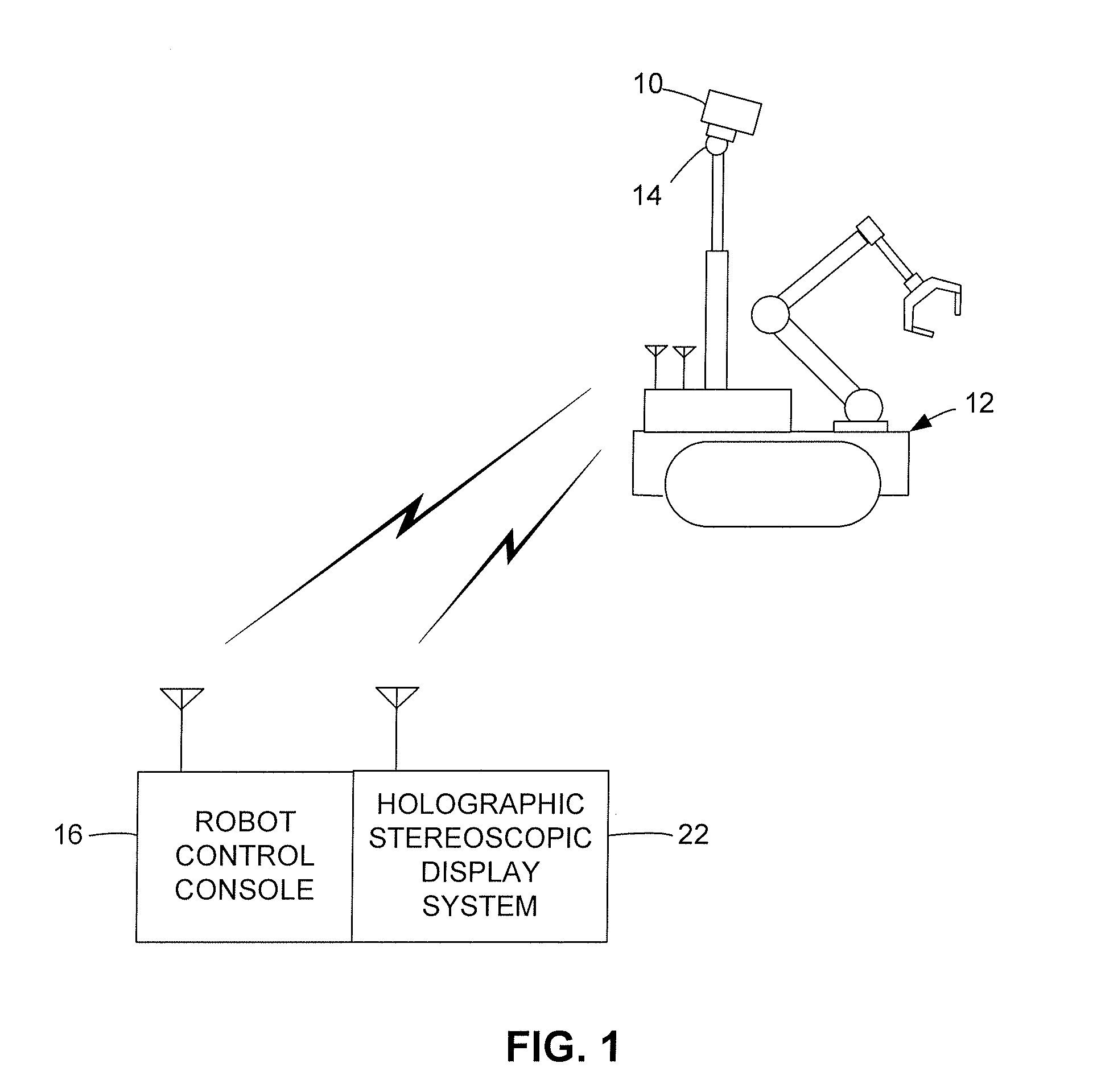
[0013]As illustrated in FIG. 1, in an exemplary embodiment of the present invention, a stereoscopic camera system 10 is mounted to a remotely controllable robot 12. Camera system 10 includes a mount 14 with servomotors or similar electronically controllable actuators that can point (e.g., pan and tilt) the stereoscopic cameras in various directions. Like robot 12, camera system 10 and its camera mount 14 are remotely controllable by an operator from an operator console 16. The communication link between robot 12 and console 16 can use a tethered (e.g., copper wire or optical fiber) or, alternatively, a wireless (i.e., radio) connection, as well known in the art.

[0014]Robot 12 can be of any suitable type, such as those commonly used by bomb disposal teams and hazardous materials handlers. The REMOTEC ANDROS F6A, available from Remotec of Clinton, Tenn., is an example of a suitable robot and includes an extendable arm on which camera system 10 can be mounted, a powered manipulator arm...


PUM


Abstract

A robotic vision and vision control system includes a stereoscopic camera mounted on a robot and a remote three-dimensional display system that provides the operator of the robot with a good sense of depth or distance for more precisely maneuvering the robot. The stereoscopic display system can further include an eye-tracking system that monitors the operator's eyes to determine the direction in which the operator's eyes are looking and points the camera in that direction.

Description

CROSS-REFERENCE TO RELATED APPLICATIONS[0001]The benefit of the filing date of U.S. Provisional Patent Application Ser. No. 60 / 721,511, filed Jun. 1, 2006, entitled 3-D ROBOTIC VISION AND VISION CONTROL SYSTEM, is hereby claimed, and the specification thereof incorporated herein in its entirety by this reference.BACKGROUND OF THE INVENTION[0002]1. Field of the Invention[0003]The present invention relates generally to robotics and electronic displays and, more specifically, to a 3-D robotic vision system and visual feedback control system to allow an operator to experience improved remote control of a robot.[0004]2. Description of the Related Art[0005]In many applications, a remote control robot is used to accomplish a task that is difficult or dangerous for a human to accomplish. A ready example of such is bomb investigation and disposal, such as performed by law enforcement. Another similar example of such is evaluating Improvised Explosive Devices (IEDs), such as often occurs in c...

Claims


Application Information

Patent Timeline
Patent Type & Authority Applications(United States)
IPC IPC(8): H04N13/02
CPCG06F3/013H04N13/0059H04N13/0484H04N13/0497H04N13/194H04N13/383H04N13/398
Inventor BARBER, FREDHESS, DAN
Owner BARBER FRED
Why Eureka
Try Eureka