LED illumination device

Inactive Publication Date: 2008-12-04
PYROSWIFT HOLDING CO LIMITED
6 Cites 25 Cited by

AI-Extracted Technical Summary

Problems solved by technology

However, the above conventional illumination device can't sufficiently disperse light beams of the LEDs to outside, and the structure of the conventional illumination device i...

Method used

[0025]The reflection cover 2 can uniformly disperse light beams from the LED modules 3 to outside for reduce optical energy loss. Furthermore, the isothermal vapor chamber 32 can efficiently dissipate heat to reduce chances of damaging the LEDs because of higher temperature.
[0026]In addition, the die casting lamp cover 1 is one-piece, and the number of elements of the LED illumination device is reduced. Therefore, t...

Benefits of technology

[0006]Because of using the reflection cover, the LED illumination device can uniformly disperse light beams from the LED modules to outside for reducing energy loss. Further, the isothermal vapor chamber can efficiently dissipate heat to reduce chances of damaging the...

Abstract

An LED illumination device includes a die casting lamp cover, a plurality of LED modules, a reflection cover, and a transparent module. A top surface of the die casting lamp cover protrudes forth to form a plurality of heat dissipating fins, and the LED modules are assembled in an accommodating room of the die casting lamp cover. The LED modules respectively include a LED lamp assembly and an isothermal vapor chamber. The reflection cover includes a plurality of openings surroundingly arranged on outside of the LED modules correspondingly. The transparent module are arranged under the die casting lamp cover and enclosed in the accommodating room. The LED illumination device can uniformly disperse light beams from the LED modules to outside for reducing energy loss, and further can efficiently dissipate heat to reduce chances of damaging the LEDs because of high temperature.

Application Domain

Technology Topic

Image

  • LED illumination device
  • LED illumination device
  • LED illumination device

Examples

  • Experimental program(1)

Example

[0018]Reference will now be made to the drawings to describe a preferred embodiment of the present in-mould molding touch module, in detail.
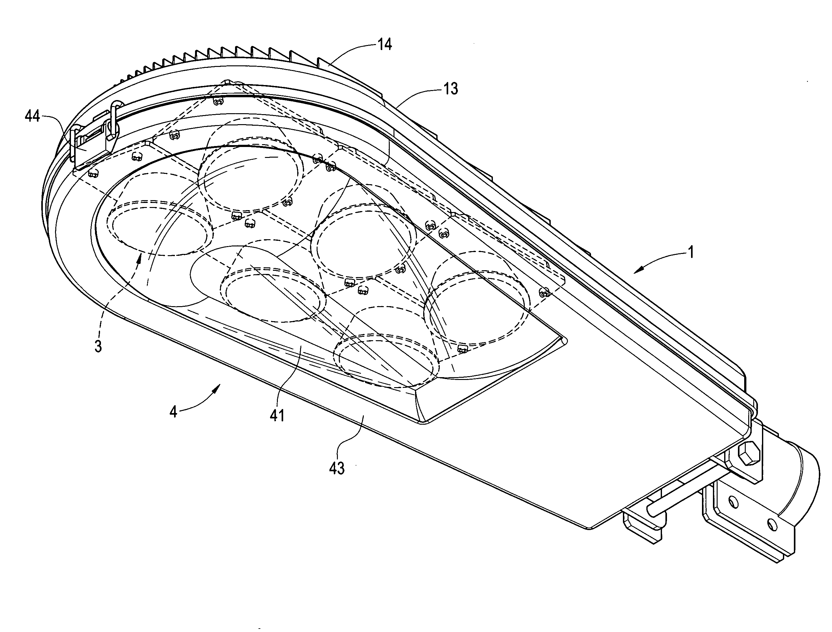
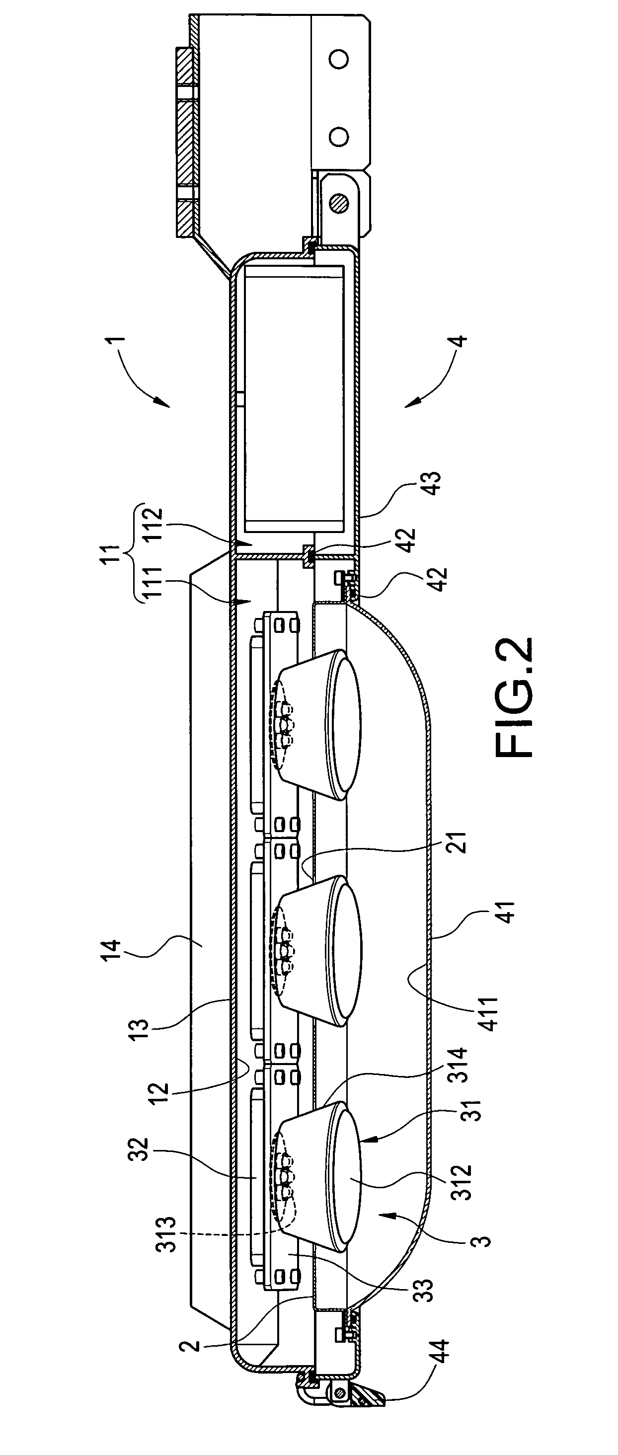
[0019]Referring to FIGS. 1 to 4, the LED illumination device includes a die casting lamp cover 1, a plurality of LED modules 3, a reflection cover 2, and a transparent module 4. The die casting lamp cover is formed an accommodating room 11. The die casting lamp cover 1 includes an inner surface 12 and a top surface 13, and a plurality of heat dissipating fins 14 are protruded out from the top surface 13. In this embodiment, the accommodating room 11 includes a first room 111 and a second room adjacent 112 to the first room 111.
[0020]The plurality of LED modules 3 are assembled in the first room 111 of the accommodating room 11 and attached on the inner surface 12 of the die casting lamp cover 1. Each LED module 3 includes a LED lamp assembly 31 and an isothermal vapor chamber 32, and the isothermal vapor chamber 32 is disposed between the LED lamp assembly 31 and the inner surface 12 of the die casting lamp cover 1.
[0021]Referring to FIG. 5, in this embodiment, the LED module 3 further include a fixing plate 33 for fixing the LED lamp assembly 31 thereon, and the isothermal vapor chamber 32 is disposed among the LED lamp assembly 31, the fixing plate 33 and the inner surface 12 of the die casting lamp cover 1. The LED modules 3 are secured on the inner surface 12 of the die casting lamp cover 1, as shown in FIG. 5, and a plurality of bolts 34 passing through the fixing plate 33 to fix on the inner surface 12 of the die casting lamp cover 1.
[0022]The LED lamp assembly 31 comprises a lamp cup 311, a lens 312, a plurality of LEDs 313, and a cover 314. In this embodiment, every LED lamp assembly 31 includes six LEDs 313. The lens 312 is arranged on the bottom end of the lamp cup 311, and the LEDs 313 are arranged on the top end of the lamp cup 311. The cover 314 has an end connected to the fixing plate 33 and extending downward to envelop on outside of the lamp cup 311 and the lens 312.
[0023]Referring to FIG. 6, the reflection cover 2 includes a plurality of openings 21 and a coating reflection surface 22. The number of the openings 21 of the reflection cover 2 is the same as the number of the LED modules 3. The openings 31 are arranged on outside of the LED modules 3 correspondingly, and the openings 31 are adjacent to the inner surface 12 of the die casting lamp cover 1. The coating reflection surface 22 is arranged corresponding to the illuminating direction of the LED modules 3.
[0024]The transparent module 4 is assembled on the die casting lamp cover 1 and enclosed in the first room 11. In this embodiment, the transparent module 4 includes a transparent cover 41, two adhesive pieces 42 and a foot cover 43. The transparent cover 41 is a transparent body, and has an inner surface 411. One adhesive piece 42 is arranged between the transparent cover 41 and the foot cover 43, and another adhesive piece 42 is arranged between the foot cover 43 and the die casting lamp cover 1, whereby the transparent module 4 can have functions of waterproof and dustproof. A lock ring 44 is arranged at the center of the outside of the foot cover 43, and the transparent module 4 and the die casting lamp cover 1 are interconnected by the lock ring 44. The reflection cover 2 is connected to the transparent cover 4 by a pressure plate and bolts.
[0025]The reflection cover 2 can uniformly disperse light beams from the LED modules 3 to outside for reduce optical energy loss. Furthermore, the isothermal vapor chamber 32 can efficiently dissipate heat to reduce chances of damaging the LEDs because of higher temperature.
[0026]In addition, the die casting lamp cover 1 is one-piece, and the number of elements of the LED illumination device is reduced. Therefore, the structure of the LED illumination device is simple and facilitates to assemble and repair.
[0027]The inner surface 411 of the transparent cover 41 is wavy, and therefore, when light beams from the LEDs 313 pass through the inner surface 411, the inner surface 411 of the transparent cover 41 can more uniformly transmit the light beams. On the other hand, depending on changing sizes or angles of the wavy, the transparent cover 41 can focus light beams from the LEDs 313 on a position.
[0028]In addition, the LED modules 3 are assembled in the first room 111, and the second room 112 can receive other elements, such as a transformer, and so on. The first room 111 and the second room 112 can separate high temperature and lower temperature to reduce chances of damaging the LEDs 313 because of high temperature.
[0029]The above description is given by way of example, and not limitation. Given the above disclosure, one skilled in the art could devise variations that are within the scope and spirit of the invention disclosed herein, including configurations ways of the recessed portions and materials and/or designs of the attaching structures. Further, the various features of the embodiments disclosed herein can be used alone, or in varying combinations with each other and are not intended to be limited to the specific combination described herein. Thus, the scope of the claims is not to be limited by the illustrated embodiments.

PUM

no PUM

Description & Claims & Application Information

We can also present the details of the Description, Claims and Application information to help users get a comprehensive understanding of the technical details of the patent, such as background art, summary of invention, brief description of drawings, description of embodiments, and other original content. On the other hand, users can also determine the specific scope of protection of the technology through the list of claims; as well as understand the changes in the life cycle of the technology with the presentation of the patent timeline. Login to view more.

Similar technology patents

Classification and recommendation of technical efficacy words

  • Reduce energy loss
  • Efficiently dissipate heat

High-precision maximum power point tracing method

ActiveCN101651436AOvercoming misjudgmentReduce energy lossPV power plantsPhotovoltaic energy generationObservation methodMppt algorithm
Owner:SUNGROW POWER SUPPLY CO LTD

Device having improved heat dissipation

InactiveUS20050117304A1Efficiently dissipate heatStatic indicating devicesInstrumental cooling apparatusOperating temperatureSurface plate
Owner:SAMSUNG SDI CO LTD

Heat-dissipating assembly structure

InactiveUS20080101035A1Efficiently dissipate heatEasily and rapidly be assemble and instalSemiconductor/solid-state device detailsSolid-state devicesHeat sinkEngineering
Owner:CHEN CHIUNG YI

Heating Blower with Electrostatic Atomizing Device

ActiveUS20080229606A1Stabilize flowEfficiently dissipate heatBurnersDrying gas arrangementsIonNanometer size
Owner:MATSUSHITA ELECTRIC WORKS LTD
Why Eureka
Try Eureka