Sensor device, server node, sensor network system, method of establishing communication path, control program, and storage medium

a sensor network and server node technology, applied in the field of sensor network system, can solve the problems of improper network establishment and inability to establish the network for home applications, and achieve the effect of safely and reliably establishing a communication path and establishing a data transfer path

Inactive Publication Date: 2008-12-04
SHARP KK
View PDF2 Cites 34 Cited by
  • Summary
  • Abstract
  • Description
  • Claims
  • Application Information

AI Technical Summary

Benefits of technology

[0035]According to the arrangement, in the sensor network, even when a communicable area of a sensor device or a server node newly or additionally set includes another sensor network such as a sensor network of an adjacent house, the sensor device or the server node to be set is prevented from being mistakenly connected to a network different from

Problems solved by technology

However, in a case where arrangements of the conventional techniques as mentioned above are used, the following problems occur.
In other words, in a case where the same system is used in a neighboring house in the communicable area of the sensor device assigned to a house, the network f

Method used


Image

  • Sensor device, server node, sensor network system, method of establishing communication path, control program, and storage medium
  • Sensor device, server node, sensor network system, method of establishing communication path, control program, and storage medium
  • Sensor device, server node, sensor network system, method of establishing communication path, control program, and storage medium

Examples


embodiment 1

[0141]In the present embodiment, sensor devices and server nodes include security level information and perform communication path establishment in accordance with the information.

[0142]

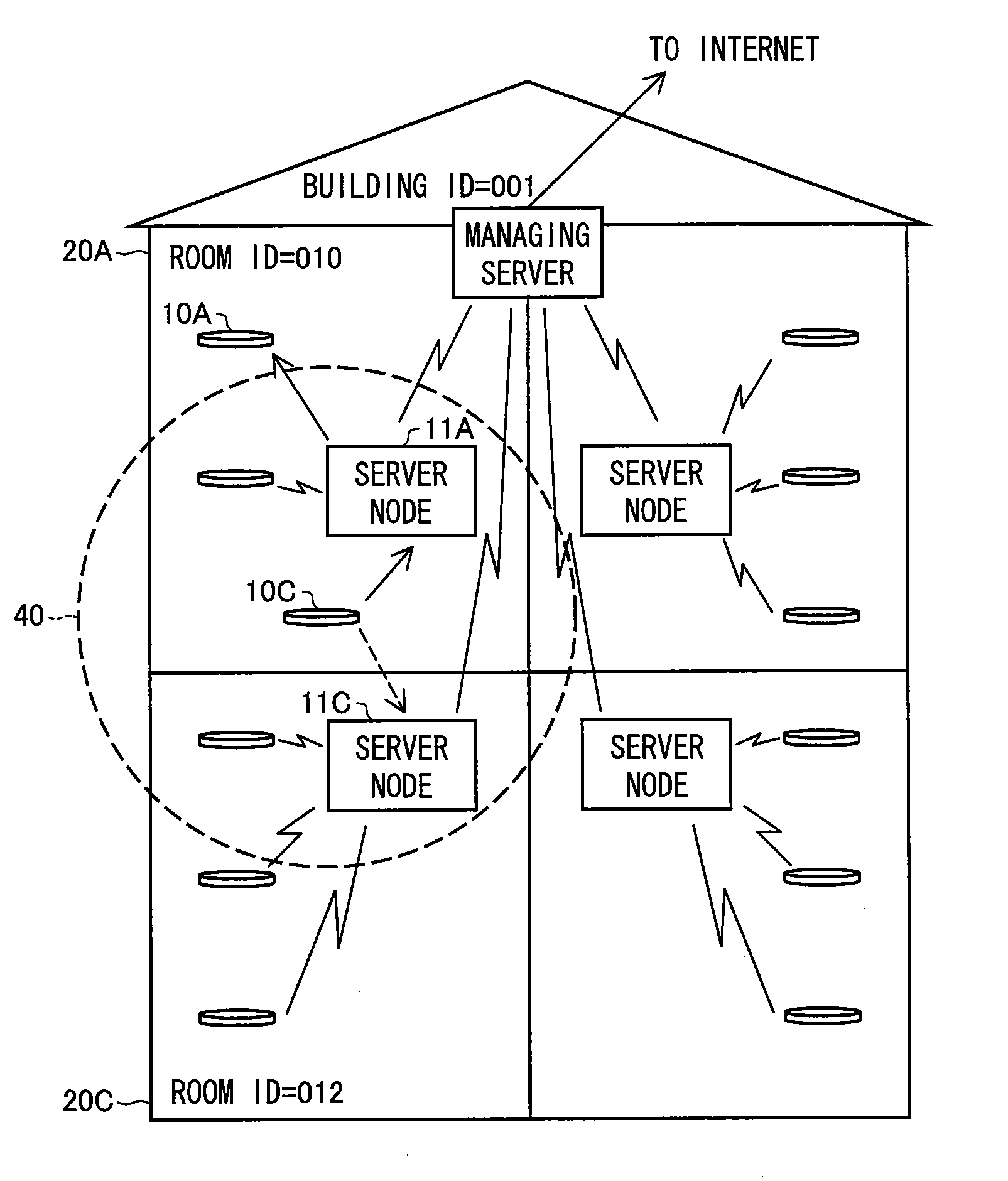
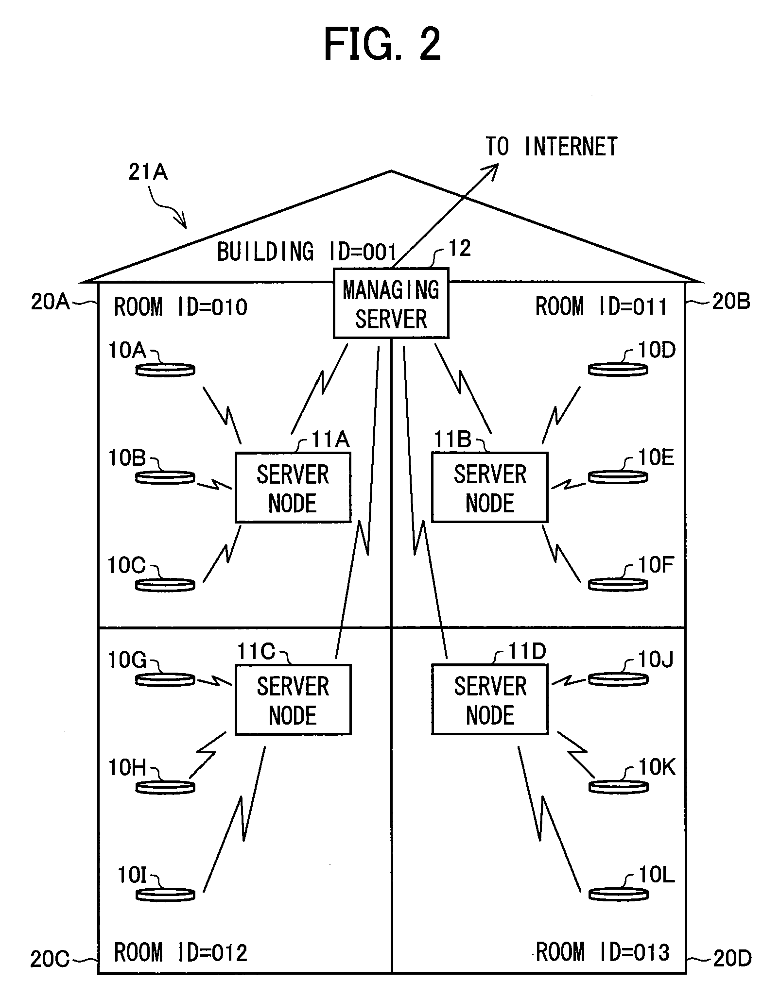
[0143]In the present embodiment, arrangements of sensor devices, server nodes, and a managing server are the same as those in the reference example except the following point, and the detailed explanations thereof are omitted.

[0144]A different point in an arrangement of the present embodiment from an arrangement in the reference example is such that, as illustrated in FIG. 12(a), in each of tables 100A through 100L in internal memories of respective control sections 3 of sensor devices 10A through 10L, security level information is stored in addition to a building ID, a room ID, and an individual ID.

[0145]As illustrated in FIG. 12(b), security level information is also stored in each of tables 110A through 110D, 110X, and 110Y respectively corresponding to server nodes 11A through 11D, 11X, and 11Y.

[...

embodiment 2

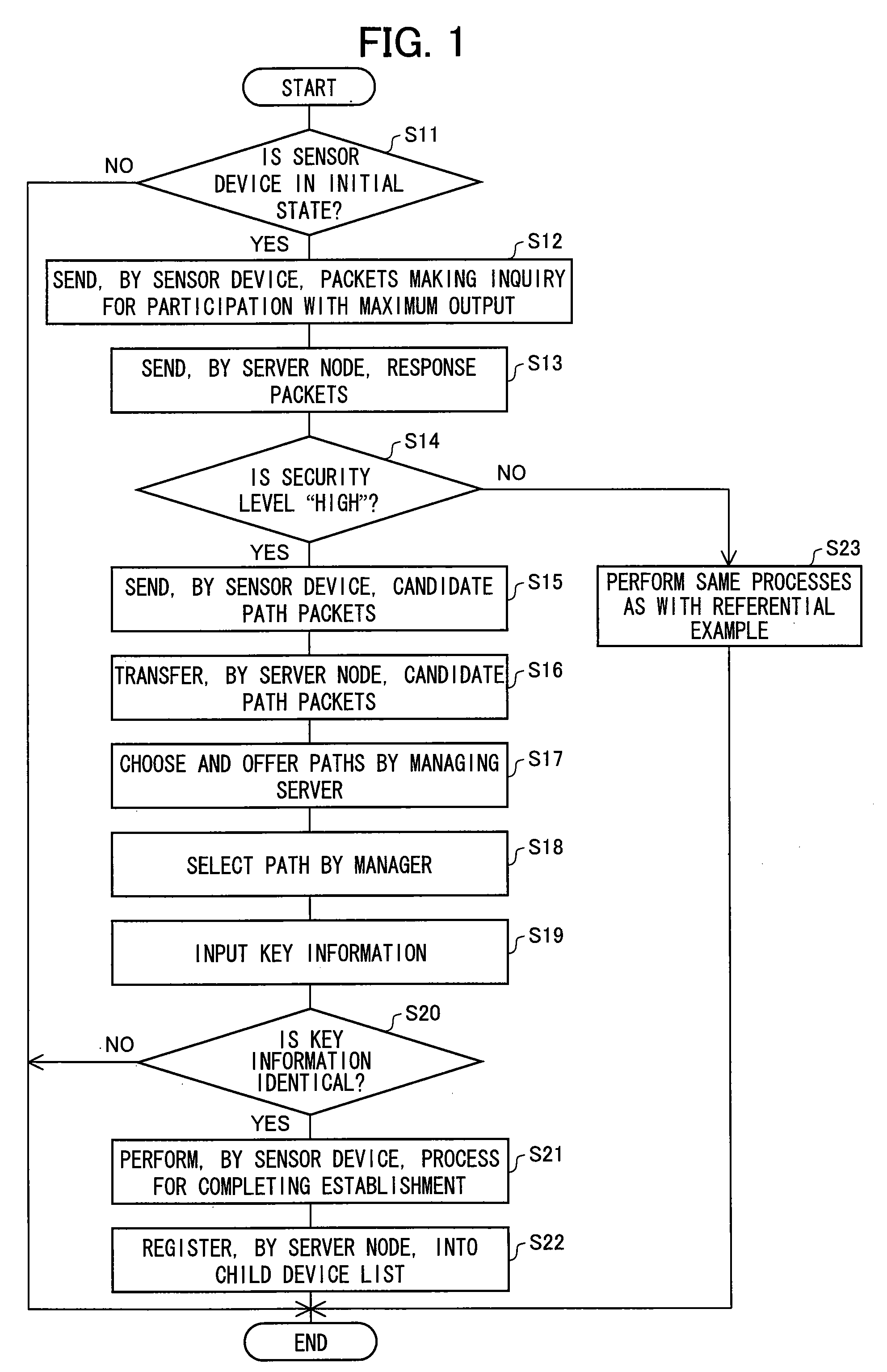
[0179]In the present embodiment, only points different from the Embodiment 1 are explained. In an arrangement of the present embodiment, the processes at S12 and S13 of the flow chart as illustrated in FIG. 1 are different from those of the Embodiment 1. In an arrangement of the Embodiment 1, a sensor device 10M sends packets making an inquiry for participation one time with a maximum output, and a server node that can correspond responds to the packets only once. On the other hand, in the present embodiment, the sensor device 10M sends packets making an inquiry for the participation a plurality of times by reducing the transmission output stepwise, after first sending packets making the inquiry for the participation with the maximum output.

[0180]

[0181]In an initial state, a security level of the sensor device 10M is set to “high”.

[0182]FIG. 16 is a flow chart illustrating a procedure in which the sensor device 10M establishes a communication path.

[0183]Procedures 1 through 3 are th...


PUM


Abstract

For the purpose of allowing a sensor device (10) to carry out wireless communication with a server node (11), the sensor device (10) makes an inquiry about the server node (11) connectable to the sensor device (10) (S12). The server node (11) responds to the sensor device (10) (S13). The sensor device (10) transmits a result of the inquiry as a candidate list (S15). The server node (11) transfers the candidate list to a top node (S16). The top node receives key information and selection information selected from the candidate list, and transmits the key information and the selection information to the server node (11) selected (S19). The server node (11) transfers to the sensor device (10) the selection information, the key information, and a building ID and a room ID of the server node (11). The sensor device (10) determines whether the key information received agrees with sensor device key information (S20). When the key information agrees with the sensor device key information, the sensor device (10) notifies, to the server node (11), the agreement and an individual ID of the sensor device (10), and stores the building ID and the room ID (S21). This makes it possible to provide a sensor network system in which a communication path is safely and reliably established even when a different network exists in a communication area and a method of establishing the communication path.

Description

[0001]This Nonprovisional application claims priority under U.S.C. § 119(a) on Patent Application No. 310612 / 2006 filed in Japan on Nov. 16, 2006, the entire contents of which are hereby incorporated by reference.FIELD OF THE INVENTION[0002]The present invention relates to a sensor network system including a sensor device having a wireless communication function, and a method of establishing a communication path in the sensor network system. More specifically, the present invention relates to a sensor network system and a method of establishing a communication path which are for safely and reliably establishing a communication path used in transmitting / receiving detection data detected by the sensor device.BACKGROUND OF THE INVENTION[0003]A sensor network system includes many sensor devices (also called sensor modules) each having a wireless communication function. The sensor network system is used for various purposes in every field, for example, crime-prevention, nursing care, ene...

Claims


Application Information

Patent Timeline
IPC IPC(8): H04Q7/00H04W8/00H04W84/18
CPCH04L12/2807H04L12/2838H04L29/12047H04L29/12254H04L29/12792H04L61/15H04L61/2038H04L61/60H04L61/609H04L2012/2841H04W8/005H04W84/18H04L61/45H04L61/5038H04L2101/60H04L2101/69
Inventor ISHIDA, AKIHITO
Owner SHARP KK
Why Eureka
Try Eureka