Stator-rotor assembly having surface feature for enhanced containment of gas flow and related processes

Active Publication Date: 2008-12-04
GENERAL ELECTRIC CO
View PDF18 Cites 11 Cited by
  • Summary
  • Abstract
  • Description
  • Claims
  • Application Information

AI Technical Summary

Problems solved by technology

As alluded to above, the leakage of the hot gas by this pathway is disadvantageous for a number of reasons.
First, the loss of hot gas from the working gas stream causes a resultant loss in energy available from the turbine engine.
Second, ingestion of the hot gas into turbine wheel-spaces and other cavities can damage components which are not designed for extended exposure to such temperatures, such as the nozzle structure support and the rotor wheel.
While coolant air from the secondary flow circuit is very beneficial for the reasons discussed above, there are drawbacks associated with its use as well.
For example, the extraction of air from the compressor for high pressure cooling and cavity purge air consumes work from the turbine, and can be quite costly in terms of engine performance.
Moreover, in some engine configurations, the compressor system may fail to provide purge air at a sufficient pressure during at least some engine power settings.

Method used


Image

  • Stator-rotor assembly having surface feature for enhanced containment of gas flow and related processes
  • Stator-rotor assembly having surface feature for enhanced containment of gas flow and related processes
  • Stator-rotor assembly having surface feature for enhanced containment of gas flow and related processes

Examples


Embodiment Construction

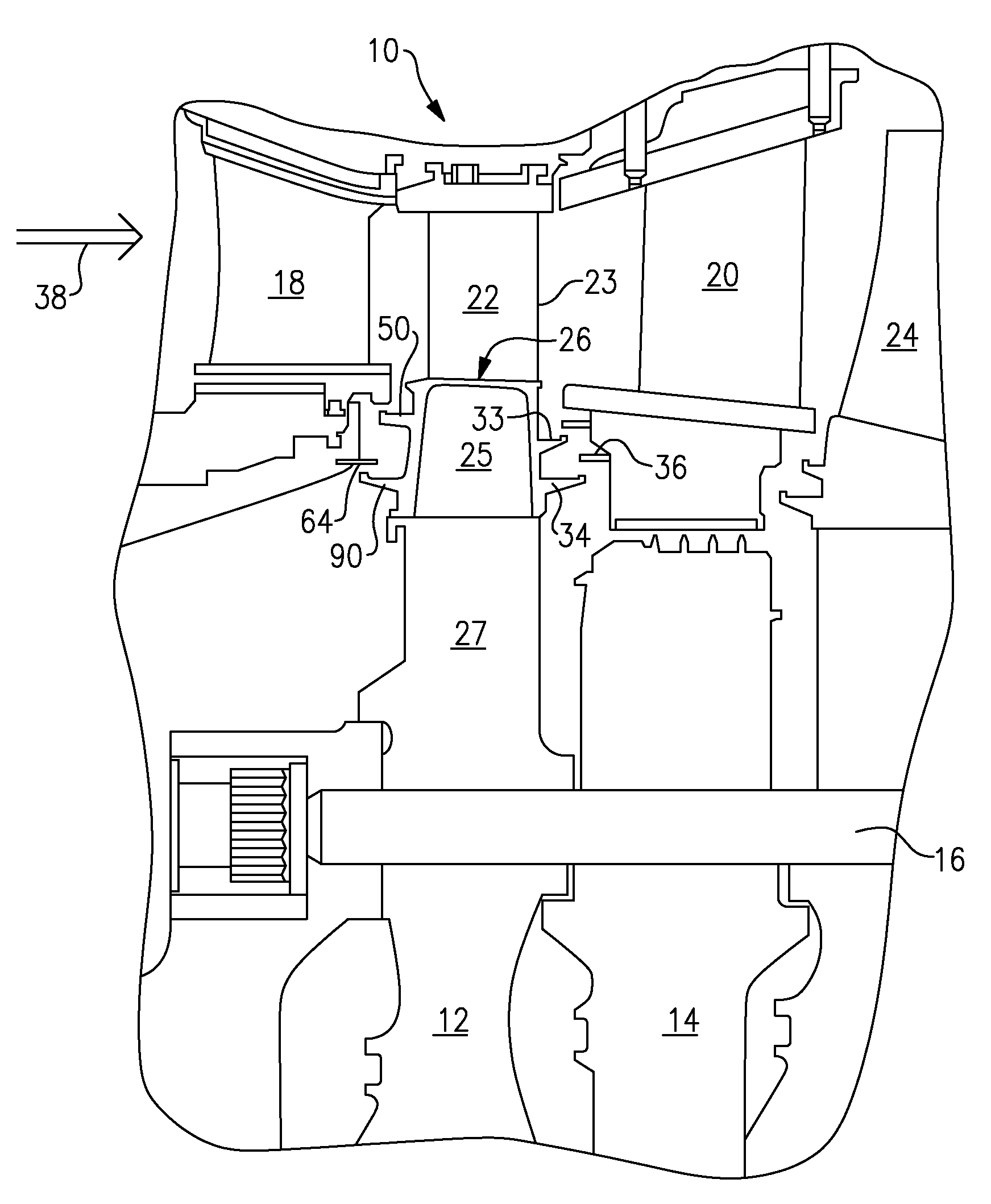
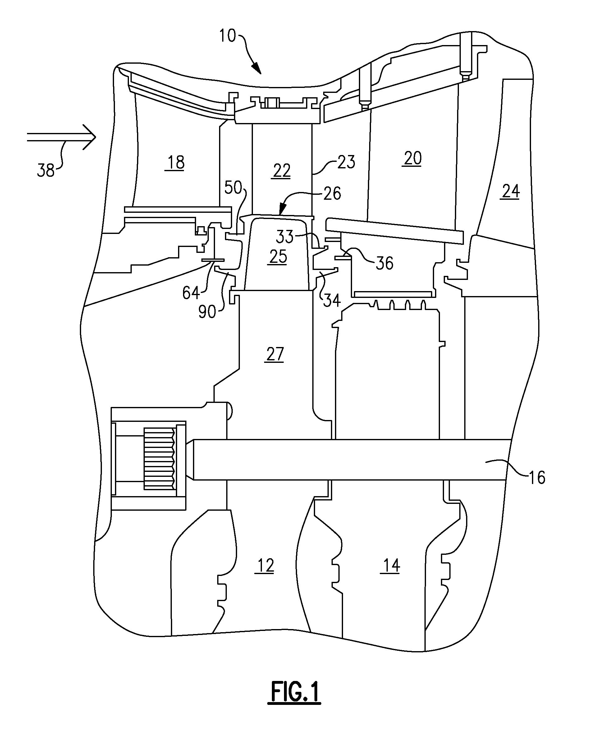
[0026]FIG. 1 is a schematic illustration of a section of a gas turbine engine, generally designated with numeral 10. The engine includes axially-spaced rotor wheels 12 and spacers 14, joined to each other by a plurality of circumferentially spaced, axially extending bolts 16. The turbine includes various stages having nozzles, for example, first-stage nozzle 18 and second-stage nozzle 20, comprised of a plurality of circumferentially spaced stator blades. Between the nozzles and rotating with the rotor are a plurality of rotor blades or buckets, the first and second-stage rotor blades 22 and 24, respectively, being illustrated.

[0027]Each rotor blade, for example, blade 22, includes an airfoil 23 mounted on a shank 25, which includes a platform 26. Some of the other detailed features of the rotor blades are not specifically illustrated here. Shank 25 includes a dovetail 27, for connection with corresponding dovetail slots formed on rotor wheel 12.

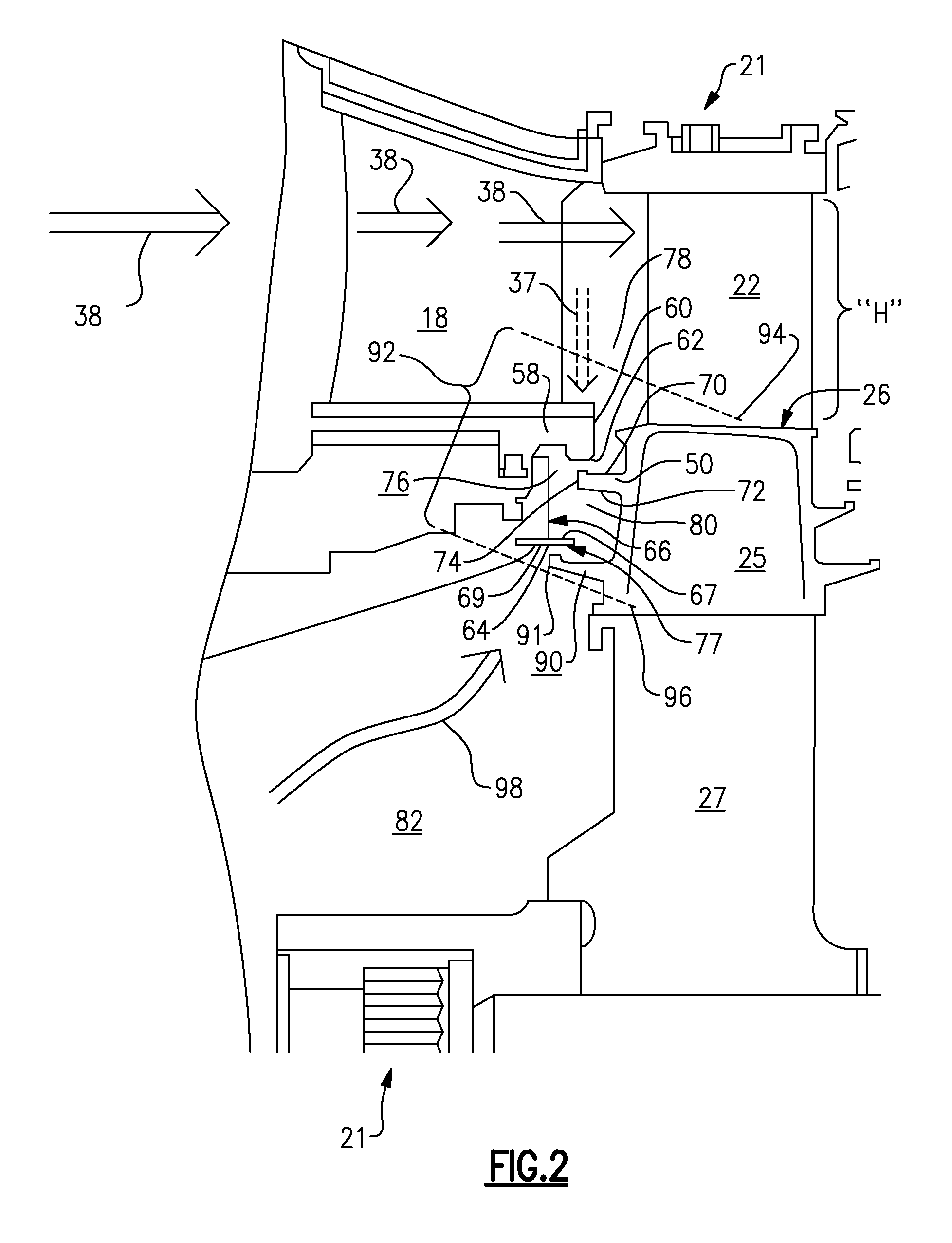
[0028]Blade or bucket 22 includes axi...


PUM


Abstract

A stator-rotor assembly which includes at least one interface region between the stator and rotor is described. At least one stator or rotor surface in the interface region includes a pattern of inverted turbulators. The inverted turbulators restrict gas flow through a gap between the stator and the rotor. Various turbomachines which can contain such a stator-rotor assembly are also described. The disclosure also discusses methods to restrict gas flow through gaps in a stator-rotor assembly utilizing the inverted turbulators.

Description

BACKGROUND OF THE INVENTION[0001]This invention relates generally to turbomachines, such as turbine engines. More specifically, the invention is directed to methods and articles for impeding the flow of gas (for example, hot gas) through selected regions of stator-rotor assemblies in turbomachines.[0002]The typical design of most turbine engines is well-known in the art. They include a compressor for compressing air that is mixed with fuel. The fuel-air mixture is ignited in an attached combustor, to generate combustion gases. The hot, pressurized gases, which in modern engines can be in the range of about 1100 to 2000° C., are allowed to expand through a turbine nozzle, which directs the flow to turn an attached, high-pressure turbine. The turbine is usually coupled with a rotor shaft, to drive the compressor. The core gases then exit the high pressure turbine, providing energy downstream. The energy is in the form of additional rotational energy extracted by attached, lower pressu...

Claims


Application Information

Patent Timeline
IPC IPC(8): F01D5/22
CPCF01D5/081F01D11/001Y02T50/676F05D2250/291F05D2250/241F05D2240/127Y02T50/60
Inventor BUNKER, RONALD SCOTT
Owner GENERAL ELECTRIC CO
Why Eureka
Try Eureka