System and method of controlling an upshift in automatic transmission

a technology of automatic transmission and control system, which is applied in the direction of instruments, mechanical equipment, digital data processing details, etc., can solve the problems of inability to directly detect the lack of engagement capacity, and inability to consider, so as to accurately determine the variation of engagement capacity, reduce size and weight, and stabilize the shift feeling

Active Publication Date: 2008-12-04
JATCO LTD +1
View PDF2 Cites 8 Cited by
  • Summary
  • Abstract
  • Description
  • Claims
  • Application Information

AI Technical Summary

Benefits of technology

[0006]It is an object of the present invention to provide a system and method of controlling an upshift in an automatic transmission, which can accurately determine variation in engagement capacity of a disengagement-side friction element or an engagement-side friction element and carry out a learning control on the basis of the determination of variation in engagement capacity, and thereby can ensure a stable shift feeling and can be reduced in size and weight.

Problems solved by technology

Therefore, it is not possible to directly detect lack of the engagement capacity of the friction element which is caused due to deterioration of friction coefficient μ. Actual engagement capacity of the friction element is given by the following formula: engagement capacity (engaging force)=friction coefficient μ X engagement pressure.
Further, even when engine racing is detected in the range in which the engagement pressure in the engagement-side friction element is larger than the engagement pressure in the disengagement-side friction element, the cause of the engine racing would not usually be the lack of the engagement capacity of the engagement-side friction element and might be the lack of the engagement capacity of the disengagement-side friction element.
That is, it cannot be considered that the determination of the cause of engine racing in the above-described conventional art is accurate.
Even if the learning control is conducted on the basis of the determination of the cause of engine racing as described in the conventional art, the shift of the friction elements could not always be carried out at accurate timing.
In the shift control system of Japanese Patent Application First Publication No. 7-12209, the number of friction elements and parts of the system must be increased, whereby it is not possible to reduce the size and weight of the system.

Method used


Image

  • System and method of controlling an upshift in automatic transmission
  • System and method of controlling an upshift in automatic transmission
  • System and method of controlling an upshift in automatic transmission

Examples


Embodiment Construction

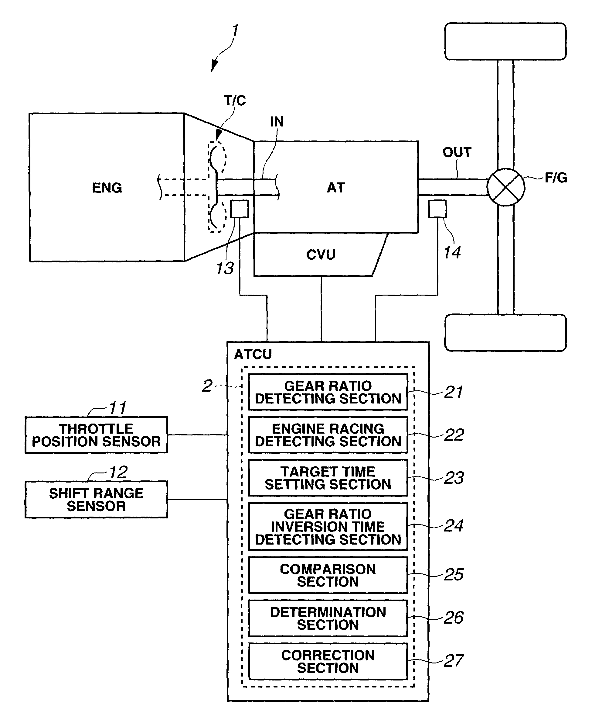
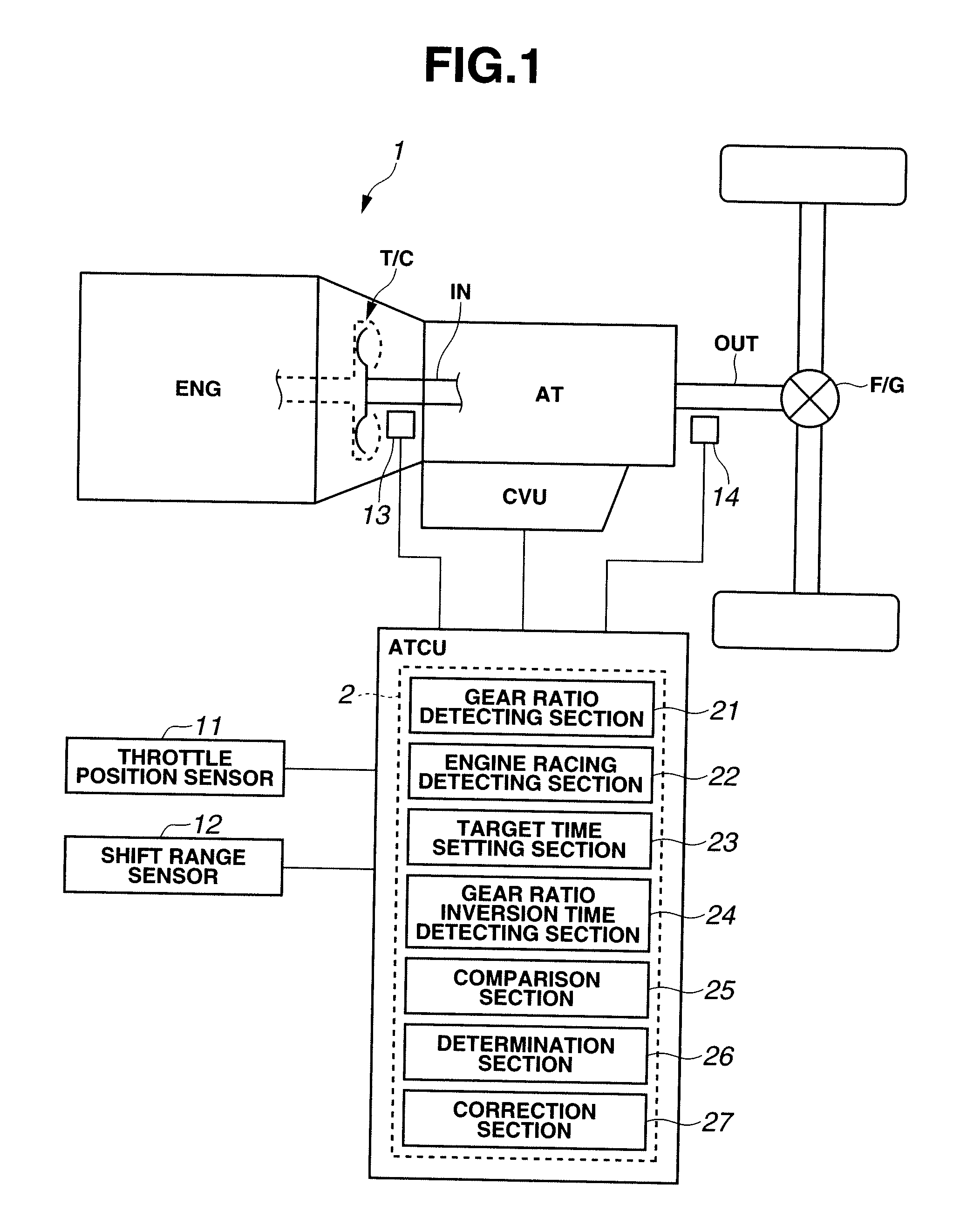
[0030]With reference to the accompanying drawings, an embodiment of an upshift control system and method for an automatic transmission, according to the present invention is explained. FIG. 1 is a schematic diagram showing a construction of the upshift control system of the embodiment which is applied to a drive system of a vehicle.

[0031][Drive System]

As illustrated in FIG. 1, drive system 1 includes engine ENG, automatic transmission AT, automatic transmission controller ATCU and various sensors 11 to 14. Automatic transmission AT is a multiple-speed automatic transmission including, for instance, five forward gears and one reverse gear.

Automatic transmission AT includes torque converter T / C, a planetary gear mechanism (not shown) and control valve unit CVU. An output torque of engine ENG is inputted to input shaft IN of automatic transmission AT via torque converter T / C. The planetary gear mechanism changes the rotation inputted through input shaft IN at gear ratio G corresponding...


PUM


Abstract

An upshift control system for use in an automatic transmission including first and second friction elements, the upshift control system including a control unit that determines variation in an engagement capacity of the first friction element or an engagement capacity of the second friction element on the basis of combination of occurrence or non-occurrence of engine racing and compared lengths between a first time that elapses from output of a shift command to a start of an inertia phase and a second time that elapses from the out output of a shift command to a start of change in an actual gear ratio toward a target gear ratio to be achieved after the shifting, and performs a learning correction of a command pressure for the first friction element or a command pressure for the second friction element on the basis of the determination result.

Description

BACKGROUND OF THE INVENTION[0001]The present invention relates to an upshift control system for an automatic transmission.[0002]There have been conventionally proposed upshift control systems for an automatic transmission. Japanese Patent Application First Publication No. 10-184882 (corresponding to U.S. Pat. No. 6,041,275) discloses an upshift control system for an automatic transmission which performs learning control of shift (changeover) timing for friction elements in the automatic transmission in order to provide a good shift feeling upon an upshift operation. In this conventional system, when engine racing is detected in a range in which an engagement pressure in an engagement-side (apply-side) friction element is larger than an engagement pressure in a disengagement-side (release-side) friction element, it is determined that the engine racing is caused due to lack of an engagement capacity of the engagement-side friction element, and therefore, the engagement pressure in the...

Claims


Application Information

Patent Timeline
Patent Type & Authority Applications(United States)
IPC IPC(8): B60W10/02F16H59/24F16H59/42F16H59/68F16H61/06F16H61/68F16H61/684F16H61/686
CPCF16H61/061Y10T477/6414F16H2061/0477F16H2061/0087F16H61/04F16H61/06F16H61/00
Inventor PARK, CHEOLSATO, OSAMU
Owner JATCO LTD
Why Eureka
Try Eureka