Side collision avoidance system

a technology of collision avoidance and side view mirror, which is applied in the direction of control system, testing/monitoring control system, process and machine control, etc., can solve the problems of limited view provided by the side view mirror, not all drivers take the time to look, etc., and achieve the effect of avoiding side collisions

Inactive Publication Date: 2008-12-04
VISTEON GLOBAL TECH INC
View PDF8 Cites 58 Cited by
  • Summary
  • Abstract
  • Description
  • Claims
  • Application Information

AI Technical Summary

Benefits of technology

[0015]In a further aspect, the present invention encompasses a method for avoiding side collisions. The method includes monitoring from a direction sensor a direction signal corresponds to a direction of motion of the vehicle; monitoring from an external detector a detector signal corresponding to the a location of objects outside of the vehicle; comparing the direction signal to the detector signal; sending an avoidance signal to a braking control system if the direction signal indicates that the motor vehicle is heading toward the location at least one of the objects; and activating appropriate braking devices coupled to the braking control system to direct the vehicle away from the object.

Problems solved by technology

However, not all drivers take the time to look to see if the adjacent lane is clear.
In addition, even if they do look, the view provided by a side view mirror is limited and may not show the entire lane adjacent to the motor vehicle.
To check the blind spot, the driver is required to turn their head and look over their shoulder, resulting in a potentially dangerous situation since it requires the driver to completely take their eyes off of the road ahead.
These systems do not account for those drivers who may not notice the warning signal or may attempt to change lanes despite the warning signal, possibly resulting in a side collision with the object.

Method used


Image

  • Side collision avoidance system
  • Side collision avoidance system
  • Side collision avoidance system

Examples


Embodiment Construction

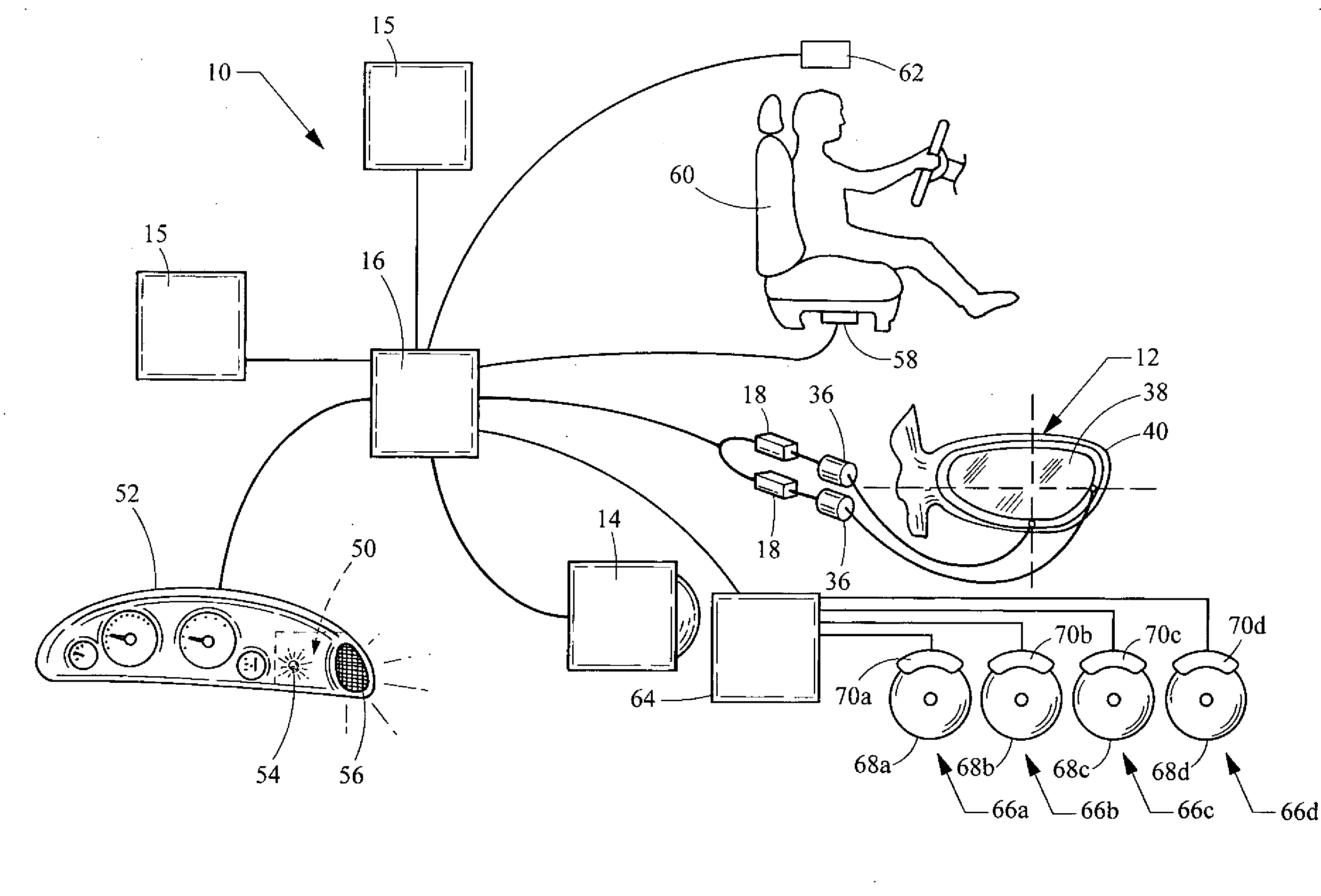
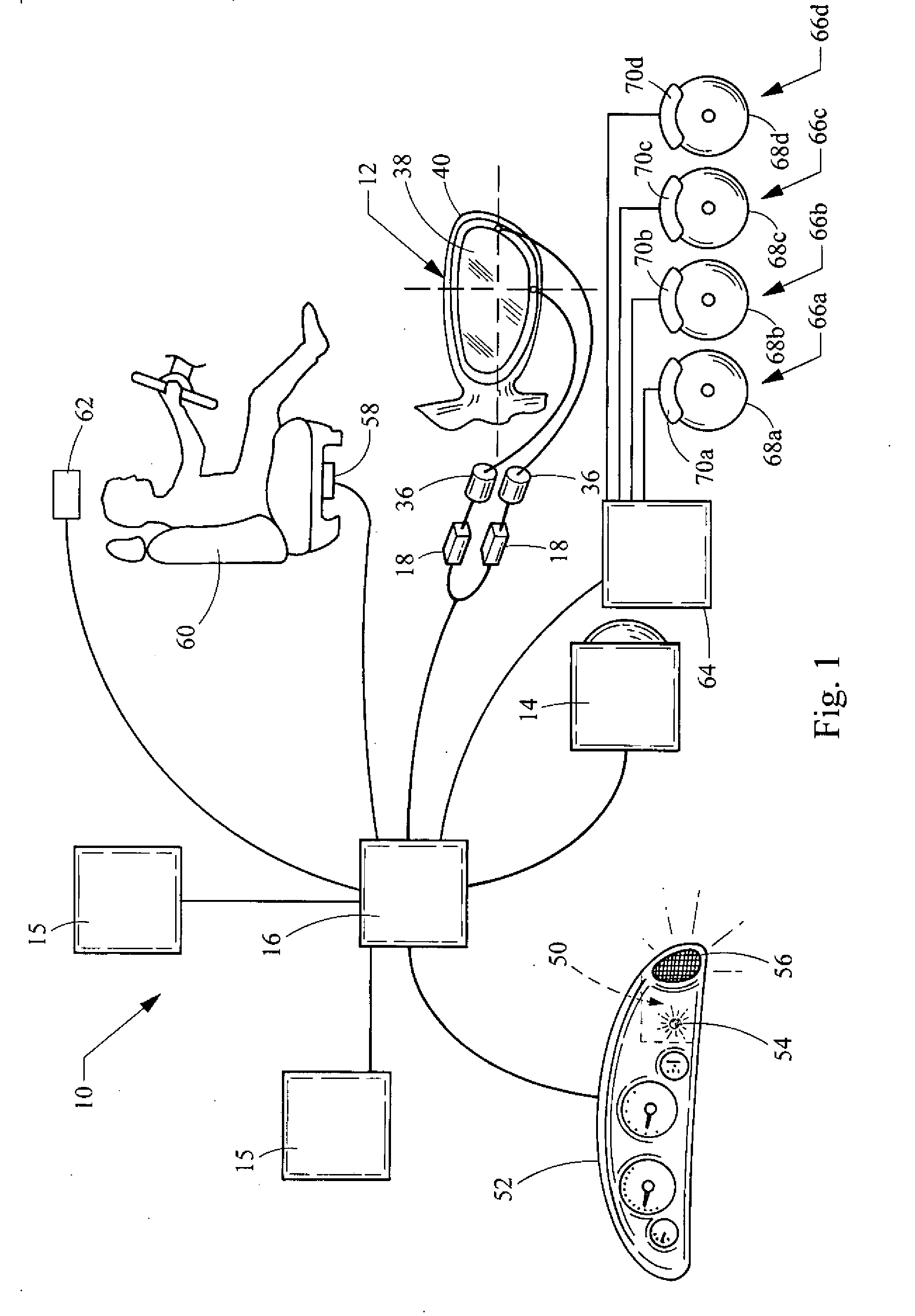
[0022]Referring now to FIG. 1, a side collision avoidance system embodying the principles of the present invention is illustrated therein and generally designated at 10. As its primary components, the side collision avoidance system 10 of a motor vehicle 11 includes an external detector 14, a direction sensor 15, and a braking control system 64. A processor 16 disposed within the motor vehicle 11 is coupled to the external detector 14, the direction sensor 15, and the braking control system 64.

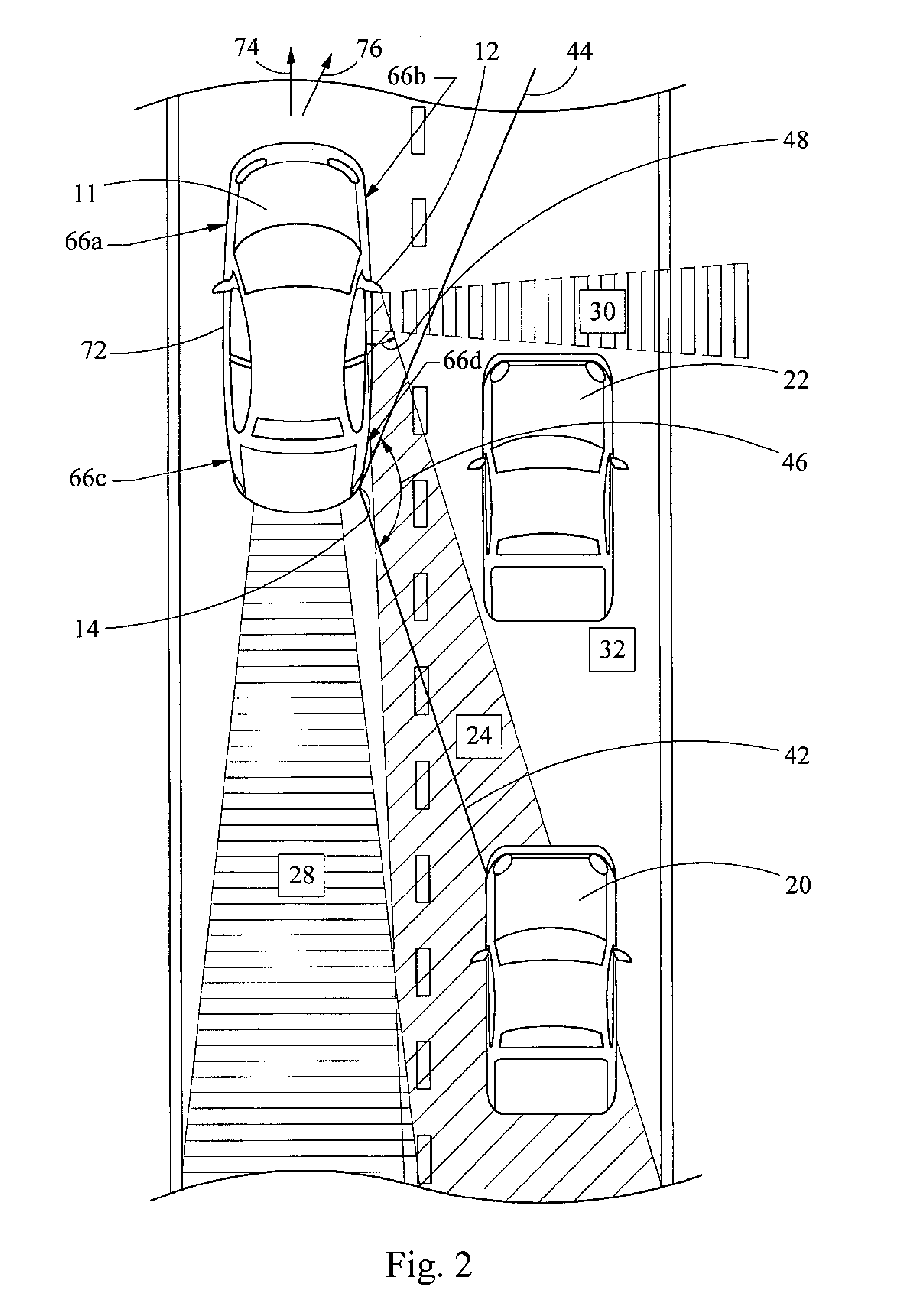
[0023]The external detector 14 is configured to generate a detector signal corresponding to a location of one or more objects, for example, a second and third motor vehicle 20 and 22 relative to the motor vehicle 11 (see FIG. 2). In doing this, the external detector 14 has a detector angle of view 46, defined between lines 42 and 44. As clearly shown in FIG. 2, both the second and third motor vehicles 20 and 22 of this example are encompassed by the angle of view 46.

[0024]The external detector...


PUM


Abstract

A motor vehicle side collision avoidance system for avoiding collisions with objects. The system includes a direction sensor generating a direction signal corresponding a direction of motion of the vehicle, an external detector generating a detector signal corresponding to a location of objects outside of the vehicle, and a braking control system including at least two independently operable braking devices coupled to respective wheels. A processor is coupled to the direction sensor, the external detector, and the braking control system. The processor receives the direction and detector signals and is configured to send an avoidance signal to the braking control system based on the direction and detector signals. Upon receipt of the avoidance signal, the braking control system activates appropriate braking devices to avoid collision with the objects.

Description

BACKGROUND[0001]1. Field of the Invention[0002]The present invention generally relates to intelligent transportation systems. More specifically, the invention relates to collision avoidance systems for motor vehicles.[0003]2. Description of Related Art[0004]When a driver of a motor vehicle desires to change lanes, the driver ordinarily should first glance in an appropriate side view mirror to make sure the adjacent lane is clear. However, not all drivers take the time to look to see if the adjacent lane is clear. In addition, even if they do look, the view provided by a side view mirror is limited and may not show the entire lane adjacent to the motor vehicle. The portion of the adjacent lane not shown in the side view mirror is called a blind spot. To check the blind spot, the driver is required to turn their head and look over their shoulder, resulting in a potentially dangerous situation since it requires the driver to completely take their eyes off of the road ahead.[0005]To min...

Claims


Application Information

Patent Timeline
Patent Type & Authority Applications(United States)
IPC IPC(8): G08G1/16G05D3/00G06F17/00B60W10/18
CPCB60R1/00B60R2300/101B60R2300/301B60R2300/302B60R2300/8026B60R2300/804B60R2300/8093B60T7/22B60T8/4809B60W10/18B60W30/09B60W50/16B60W2420/52G08G1/16G08G1/167
Inventor MADAU, DINU PETREASHRAFI, BEHROUZ
Owner VISTEON GLOBAL TECH INC
Why Eureka
Try Eureka