Electric tool

a technology of electric tools and electric motors, applied in the field of electric tools, can solve the problems of inability to solve the problem of easy to occur, and the inability to inhibit the intrusion of extraneous matter into the housing, so as to achieve efficient cooling prevent the increase in the temperature of the electric motor, and detect the effect of the problem easily

Inactive Publication Date: 2008-12-11
HITACHI KOKI CO LTD
View PDF15 Cites 22 Cited by
  • Summary
  • Abstract
  • Description
  • Claims
  • Application Information

AI Technical Summary

Benefits of technology

[0028]According to such a configuration, intrusion of extraneous matter into the housing can be prevented thoroughly, so long as the cover is attached to the housing during work performed in an environment with much extraneous matter, to thus simultaneously close both the air inlets and the air outlets and prevent occurrence of various problems resultant from intrusion of extraneous matter, such as a failure. Further, so long as the cover is formed from a soft material, the cover can also be caused to act as a protector. In addition, so long as several typ

Problems solved by technology

Such a problem easily takes place in a working environment where there is much extraneous matter, such as dust or metal powder.
The air inlet still remains open, and intrusion of extraneous matter from the air inlet into the housing cannot be hinde

Method used


Image

  • Electric tool
  • Electric tool
  • Electric tool

Examples


first embodiment

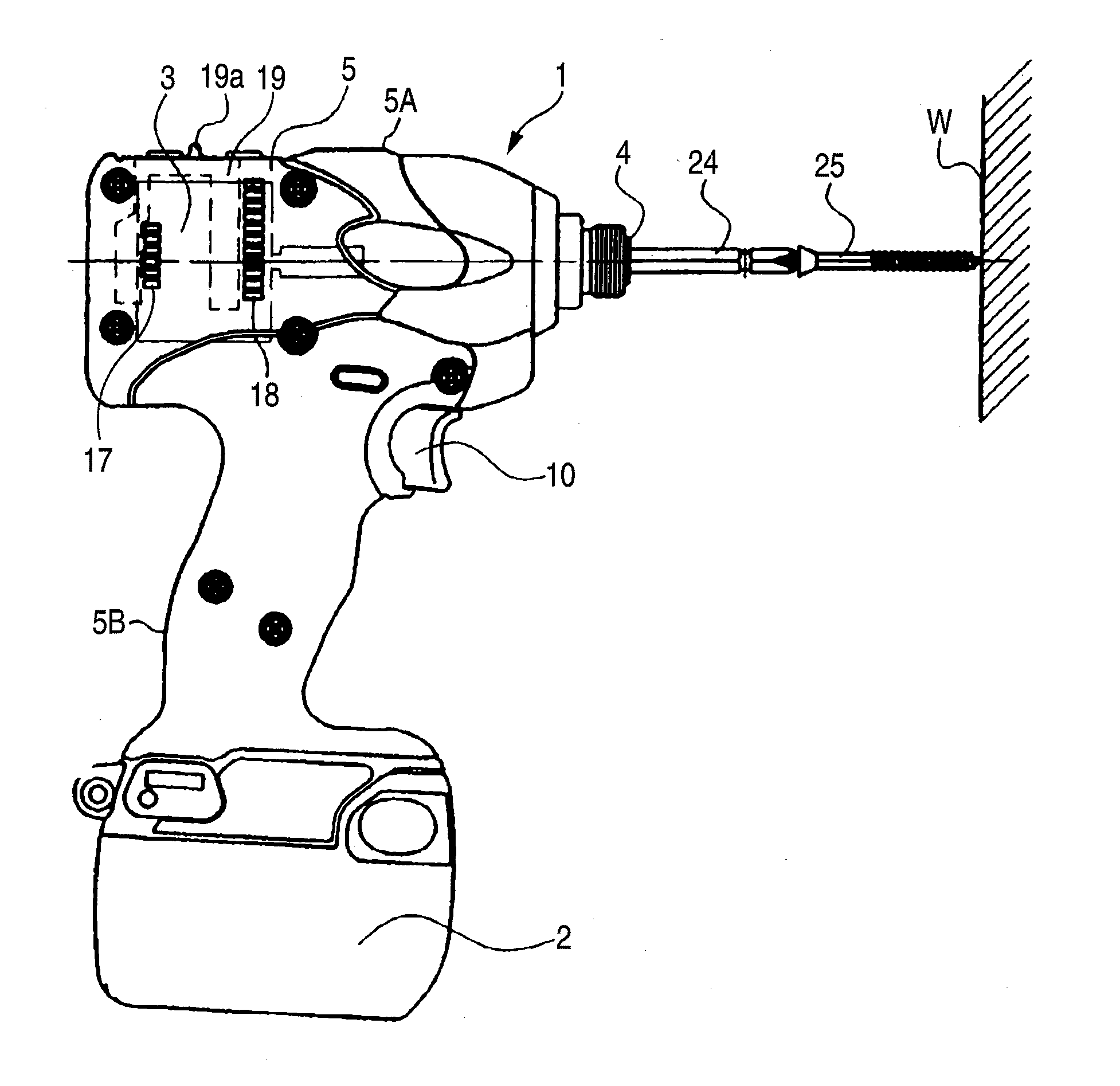
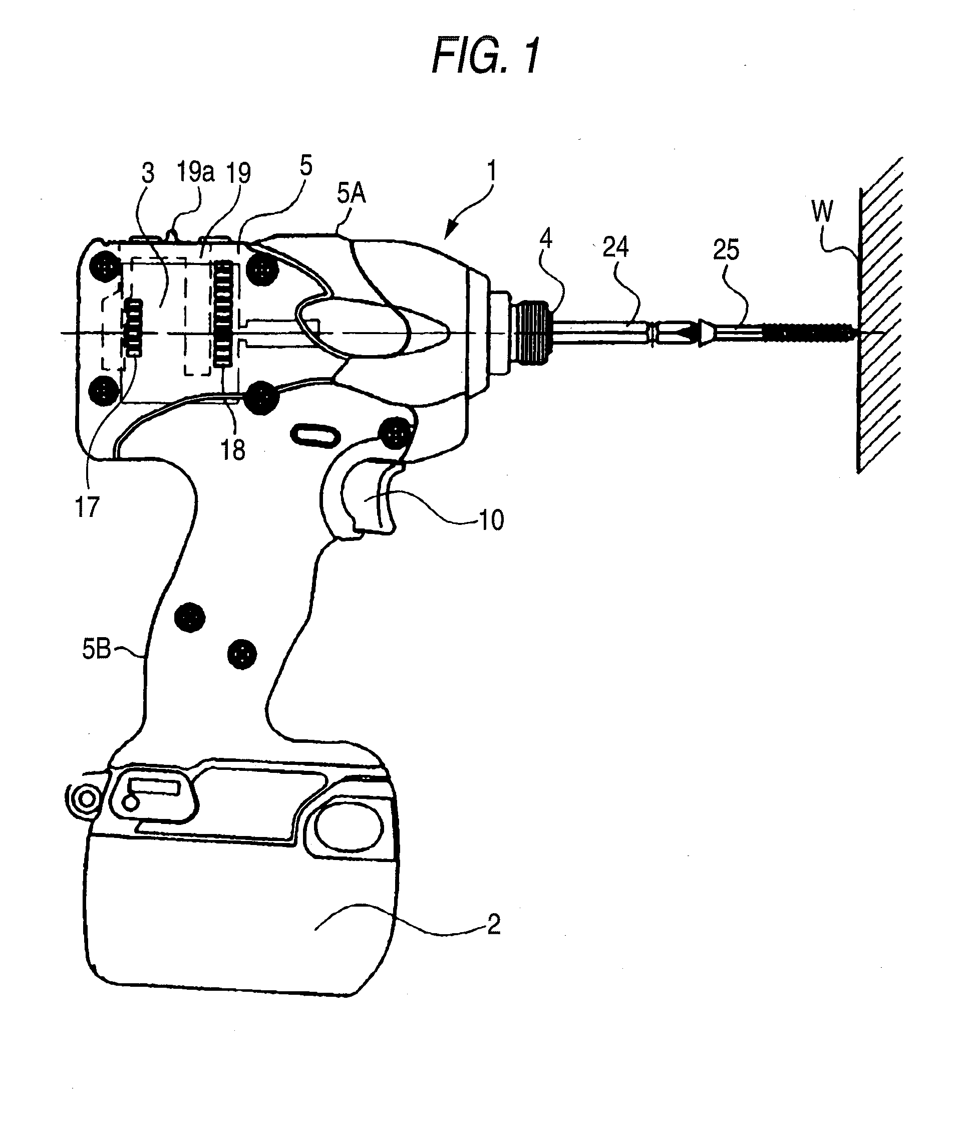
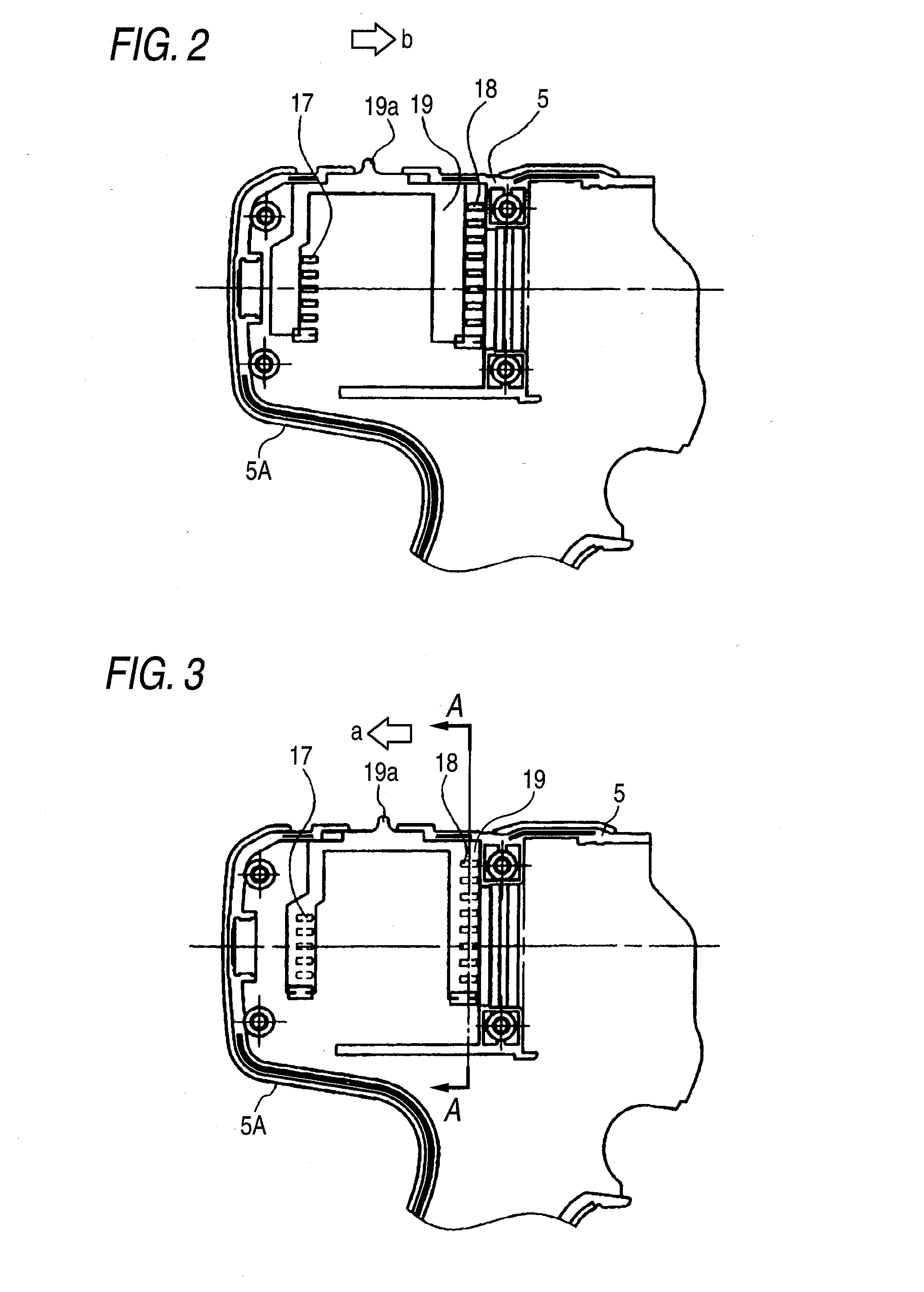
[0044]FIG. 1 is a side view of an impact driver that is an embodiment (first embodiment) of an electric tool; FIG. 2 is fragmentary internal drawing of a housing achieved when air inlets and air outlets of the impact driver are opened; FIG. 3 is a fragmentary internal drawing of the housing achieved when the air inlets and the air outlets of the impact driver are closed; and FIG. 4 is a cross-sectional view taken along line A-A shown in FIG. 3.

[0045]The impact driver 1 shown in FIG. 1 has a housing 5 that assumes the shape of the letter T when viewed sideways and that is formed from a resin. An electric motor 3 serving as a drive source is housed in a sideways position within a body 5A of the housing 5. A battery 2 is removably attached to a lower end of a handle 5B extending downwardly, in an integrated fashion, from the body 5A of the housing 5. A switch 10 that toggles on or off a power supply from the battery 2 to the electric motor 3, to thus activate / deactivate the electric mo...

second embodiment

[0053]A second embodiment will be described by reference to FIGS. 5 through 7.

[0054]FIG. 5 is a fragmentary internal view of a housing of an impact driver according to a second embodiment; and FIGS. 6 and 7 are cross-sectional views taken along line B-B shown in FIG. 5, wherein FIG. 6 shows a state where both the air inlets and the air outlets are opened and FIG. 7 shows a state that both the air inlets and the air outlets are closed.

[0055]The present embodiment is characterized in that a cover 21 is rotated in a circumferential direction along the inside of the housing 5, thereby simultaneously opening and closing the air inlets 17 and the air outlets 18. Air vents 21b (only air vents in mutual communication with the air outlets 18 are shown in FIGS. 6 and 7) that are selectively brought into mutual communication with the air inlets 17 and the air outlets 18 formed in the housing 5 are provided in the cover 21. A lever 21a for rotationally operating the cover 21 is formed integrall...

third embodiment

[0060]A third embodiment will be described by reference to FIGS. 8 and 9.

[0061]FIGS. 8 and 9 are fragmentary side views of an impact driver according to a third embodiment, wherein FIG. 8 shows a state where both the air inlets and the air outlets are opened and FIG. 9 shows a state that both the air inlets and the air outlets are closed.

[0062]The present embodiment is characterized in that a cover 22 is slid in a longitudinal direction along the outside of the housing 5, thereby simultaneously opening and closing the air inlets 17 and the air outlets 18. Rectangular air vents 22b (only one of the air vents is shown in FIGS. 8 and 9) that are selectively brought into mutual communication with the air inlets 17 formed in the housing 5 are provided at both ends of the cover 22. A lever 22a for sliding the cover 22 is formed integrally in a part of an upper surface of the cover 22.

[0063]In the present embodiment, in a working environment with much extraneous matter, such as dust or met...


PUM


Abstract

According to an aspect of the present invention, there is provided an electric tool including: a housing; a motor that is housed in the housing; a tip tool; a rotation transmission mechanism that transmits a rotation of the motor to the tip tool; an air inlet that is disposed on the housing to introduce a cooling air for cooling the motor from an outside of the housing; an air outlet that is disposed to discharge the cooling air; and a cover that is slidable along an inner wall or an outer wall of the housing and that is movable in a first position where the air inlet and the air outlet are opened and a second position where the air inlet and the air outlet are closed.

Description

CROSS-REFERENCE TO RELATED APPLICATIONS[0001]This application is based upon and claims a priority from prior Japanese Patent Application No. 2007-148847 filed on Jun. 5, 2007, the entire contents of which are incorporated herein by reference.BACKGROUND OF THE INVENTION[0002]1. Field of the Invention[0003]An aspect of the present invention relates to an electric tool having air inlets and air outlets that supply and discharge cooling air for cooling an electric motor serving as a drive source and that are formed in a housing.[0004]2. Description of the Related Art[0005]FIG. 12 shows the configuration of an impact driver as an example of the electric tool.[0006]FIG. 12 is a side cross-sectional view of the impact driver. An illustrated impact driver 1 is a tool that drives a rotary impacting mechanism while taking a battery 2 as a power source and an electric motor 3 as a drive source and imparts rotation and a strike to an anvil 4, to thus intermittently transmit rotary striking forc...

Claims


Application Information

Patent Timeline
IPC IPC(8): E21B3/00
CPCB25F5/008
Inventor KOMURO, YOSHIHIROOOMORI, KATSUHIRO
Owner HITACHI KOKI CO LTD
Why Eureka
Try Eureka