Portable electric power tool

a power tool and portable technology, applied in the direction of manufacturing tools, portable drilling machines, cell components, etc., can solve the problems of contact failure, damage to electric power tools or battery packs, elastic bodies are apt to be damaged, etc., and achieve the effect of preventing vibration transmission

Active Publication Date: 2008-12-11
MAKITA CORP
View PDF5 Cites 27 Cited by
  • Summary
  • Abstract
  • Description
  • Claims
  • Application Information

AI Technical Summary

Benefits of technology

[0010]The present invention, which solves the above-described problem, provides a technology that prevents a battery pack from vibrating during the operation of the electric power tool, without contact failure between the terminals of the electric power tool and the battery pack.
[0023]A plurality of projections and / or depressions formed on the surface of the elastic member enable further considerable deformation with respect to the applied force, which leads to the further remarkable effect of preventing vibration transmission from the housing to the battery pack holder.

Problems solved by technology

Therefore, relative displacement of the connecting terminals of the electric power tool and the output terminals of the battery pack also occurs, which leads to contact failure.
Further, the elastic bodies are apt to be damaged during attaching / detaching the battery pack.
According to the technique of Japanese Patent Application Publication No. 2003-297312, vibration still occurs between the electric power tool and the battery pack during the operation of the electric power tool, which may damage the electric power tool or the battery pack.
Particularly, when the battery pack experiences continuous strong vibration, a battery cell or an electrical circuit inside the battery pack may be damaged.
As a result, problems arise in the form of premature battery cell deterioration, electrical short circuit and so forth.

Method used


Image

  • Portable electric power tool
  • Portable electric power tool
  • Portable electric power tool

Examples


Embodiment Construction

Main Features of an Embodiment of the Invention

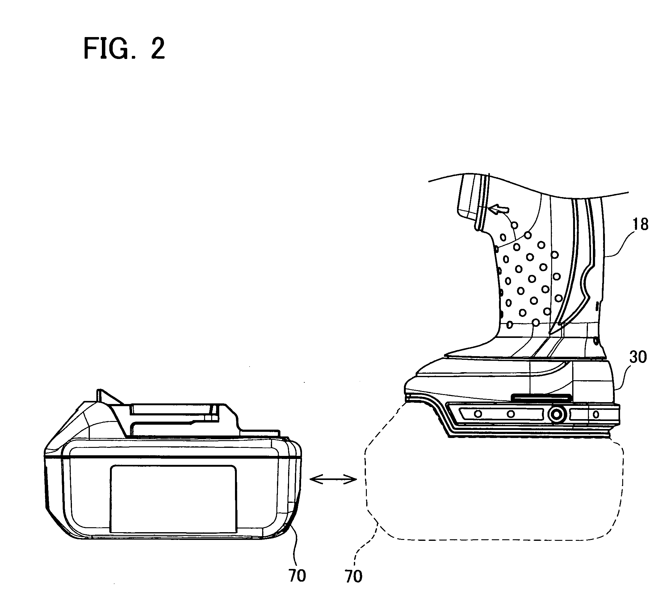
[0032](Feature 1) The connecting terminals electrically connected to the output terminals of the battery pack are fixed on the battery pack holder. The connecting terminals fixed on the battery pack holder are connected to a trigger switch and a motor provided in the housing via lead wires.[0033](Feature 2) The elastic member is formed of rubber material.[0034](Feature 3) A plurality of projections is formed on the contact surface of the elastic member and / or the contact surface of the battery pack holder with the housing.[0035](Feature 4) The battery pack holder is formed of the same material as the housing.

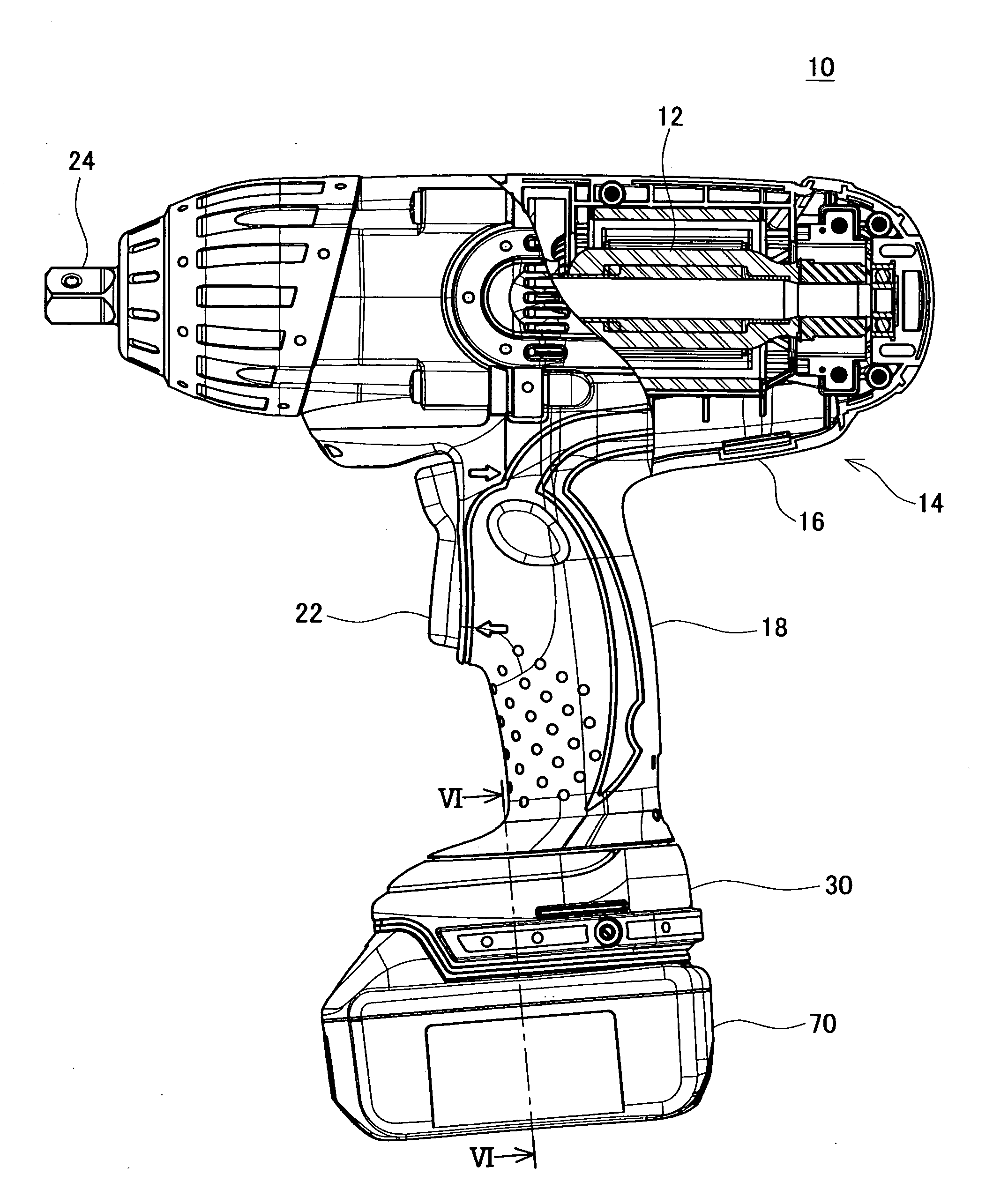
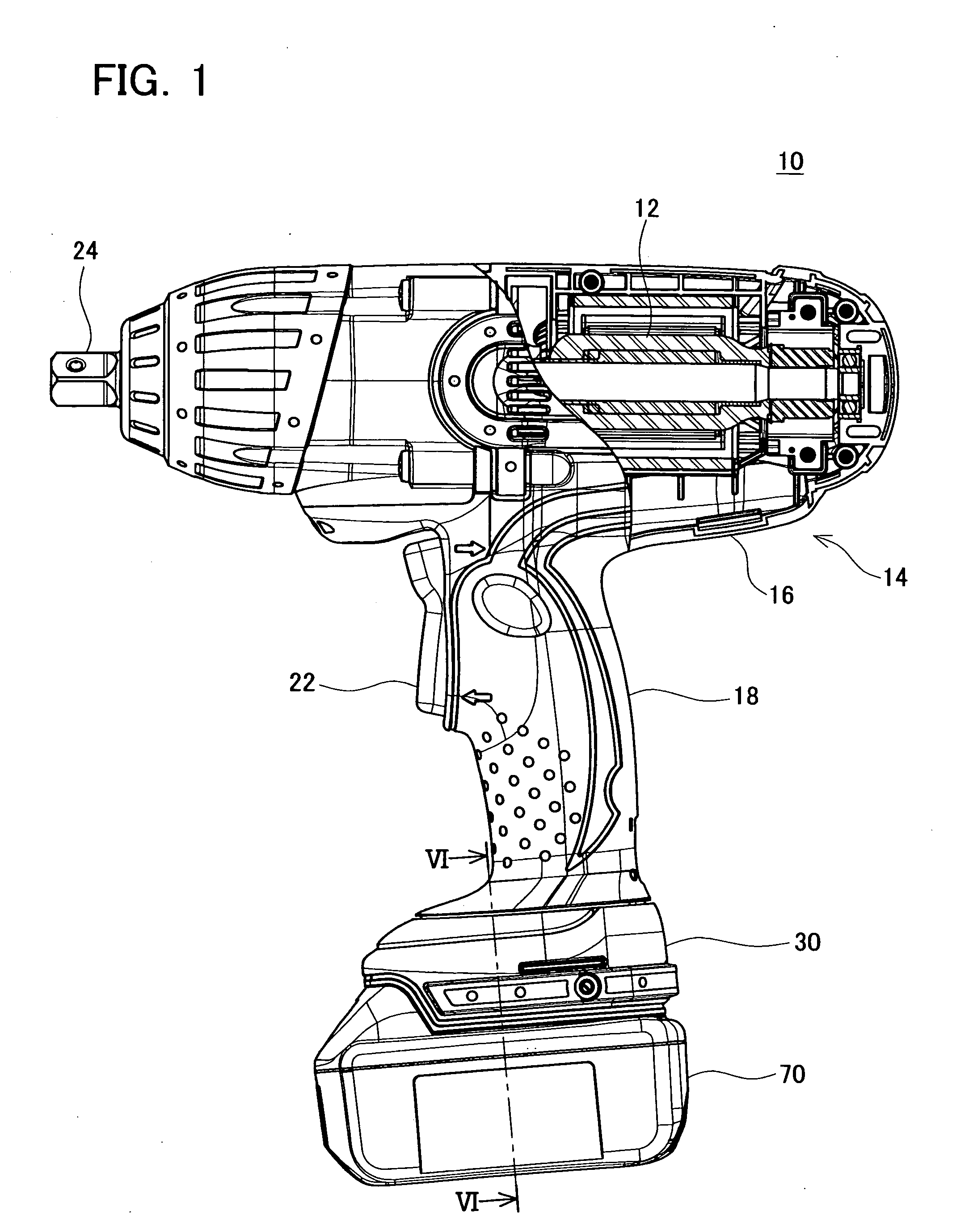
[0036]A description will be given with reference to the drawings of the electric power tool on which the present invention is executed. The electric power tool of this example is a portable electric power tool used by the user in a gripping state, in particular, a fastening tool for fastening bolts.

[0037]FIG. 1 is the side view show...


PUM

PropertyMeasurementUnit
voltageaaaaaaaaaa
elasticaaaaaaaaaa
thermal deformationaaaaaaaaaa

Abstract

A portable electric power tool powered by a battery pack, which includes: a motor that operates the tool; the housing that houses the motor; at least one elastic member that is supported by the housing; and a battery pack holder supported by the elastic member. The battery pack holder is provided with an engaging portion that is detachably engaged with the case of the battery pack and connecting terminals that are electrically connected to the output terminals of the battery pack installed by the engaging portion. Thus, vibration of the battery pack is prevented even when the electric power tool vibrates.

Description

CROSS-REFERENCE TO RELATED APPLICATION [0001]This application claims priority to Japanese Patent Application No. 2007-151149, filed on Jun. 7, 2007, the contents of which are hereby incorporated by reference into the present application.BACKGROUND OF THE INVENTION [0002]1. Field of the Invention[0003]The present invention relates to a portable electric power tool powered by a battery pack.[0004]2. Description of the Related Art[0005]In the portable electric power tool powered by a battery pack, the electric power tool and the battery pack vibrate relative to each other during the operation of the electric power tool, and the electric power tool or the battery pack may be damaged in some cases. There are also cases where contact failure occurs between output terminals of the battery pack and connecting terminals of the electric power tool connecting thereto.[0006]Regarding the above-described problem, Japanese Patent Application Publication No. H10-296660 discloses a portable electri...

Claims


Application Information

Patent Timeline
Patent Type & Authority Applications(United States)
IPC IPC(8): B23B47/00
CPCH01M2/1066B25F5/006Y02E60/10
Inventor KONDO, TOMOYUKI
Owner MAKITA CORP
Why Eureka
Try Eureka