Light emitting apparatus, method for manufacturing the light emitting apparatus, electronic device and cell phone device

a technology of light emitting apparatus and manufacturing method, which is applied in the manufacture of electrode systems, electric discharge tubes/lamps, and discharge tubes luminescnet screens, etc., to achieve the effect of reducing resin viscosity, reducing resin viscosity, and increasing specific gravity

Active Publication Date: 2008-12-11
SHARP KK
View PDF16 Cites 44 Cited by
  • Summary
  • Abstract
  • Description
  • Claims
  • Application Information

AI Technical Summary

Benefits of technology

[0049]A method for manufacturing a light emitting apparatus according to the present invention having a light emitting device mounted on a substrate or a resin package where a substrate surface or the resin package is resin-encapsulated by an encapsulating resin section added with a phosphor in such a manner to cover the light emitting device, includes the steps of mixing an optical diffusion material and a phosphor, the phosphor having greater specific gravity than the optical diffusion material, in a resin material that is used for the encapsulating resin section in such a manner to disperse the optical diffusion material and the phosphor almost evenly; and precipitating the phosphor in the resin material to a light emitting device side by the decrease of resin viscosity caused at the heat curing of the resin material and by the difference of specific gravities between the optical diffusion material and the phosphor so as to distribute the optical diffusion material at the surface side of the resin material, which is opposite from the light emitting device side, thereby achieving the objective described above.
[0050]A method for manufacturing a light emitting apparatus according to the present invention having a light emitting device mounted on a substrate or a resin package where a substrate surface or the resin package is resin-encapsulated by an encapsulating resin section added with a phosphor in such a manner to cover the light emitting device includes the steps of: covering a light emitting device mounted on a substrate or a resin package with an encapsulating resin section added with a phosphor and curing the encapsulating resin section; pouring a resin material added with an optical diffusion material into a metal mold having a recess; inserting the light emitting device mounted on the substrate or the resin package into the resin material added with the optical diffusion material with the surface side of the cured encapsulating resin section added with the phosphor facing down; and precipitating the optical diffusion material due to the decrease of resin viscosity caused at the heat curing of the resin material added with the optical diffusion material and by the difference of specific gravities between the resin material and the optical diffusion material, thereby achieving the objective described above.

Problems solved by technology

The conventional technique described above, however, has the following problems.

Method used


Image

  • Light emitting apparatus, method for manufacturing the light emitting apparatus, electronic device and cell phone device
  • Light emitting apparatus, method for manufacturing the light emitting apparatus, electronic device and cell phone device
  • Light emitting apparatus, method for manufacturing the light emitting apparatus, electronic device and cell phone device

Examples


embodiment 1

Variation of Embodiment 1

[0125]In Embodiment 1 described above, a case is described where the LED chip 6 is provided on the substrate 2. In this variation, a case will be described where the LED chip 6 is provided inside a recess section of a resin package instead of the substrate 2.

[0126]FIG. 5 is a longitudinal cross sectional view showing an exemplary essential structure of a light emitting apparatus according to the variation.

[0127]According to the light emitting apparatus 1A of the variation as shown in FIG. 5, an LED chip 6A is provided at the center of the bottom portion in the recess section of a resin package 2A, and the surface side of the recess of the resin package 2A is resin-encapsulated in such a manner to cover the LED chip 6A. An encapsulating resin section 3A, which is resin-encapsulated, is added with a phosphor, and a surface resin layer 4A is provided on the surface of the encapsulating resin section 3A similar to Embodiment 1 described above.

[0128]The surface s...

embodiment 2

Variation of Embodiment 2

[0139]Although a case where the LED chip 6 is mounted on the substrate 2 is shown in Embodiment 2 described above, a case where the LED chip 6 is mounted in a recess section of a resin package instead of the substrate 2 will be described in this variation.

[0140]Similar to the case in FIG. 5, according to the light emitting apparatus of the variation, an LED chip 6A is provided at the center of the bottom portion in the recess section of a resin package 2A, and the surface side of the recess of the resin package 2A is resin-encapsulated in such a manner to cover the LED chip 6A. An encapsulating resin section 3A, which is resin-encapsulated, is added with a phosphor, and a surface resin layer, to which at least one of an R (red) phosphor, a G (green) phosphor and a B (blue) phosphor is added, is provided on the surface of the encapsulating resin section 3A similar to Embodiment 2 described above. As a result, similar to Embodiment 2, the surface of the light ...

example 1

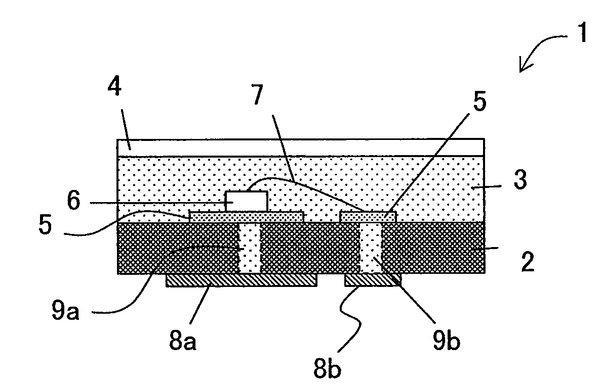
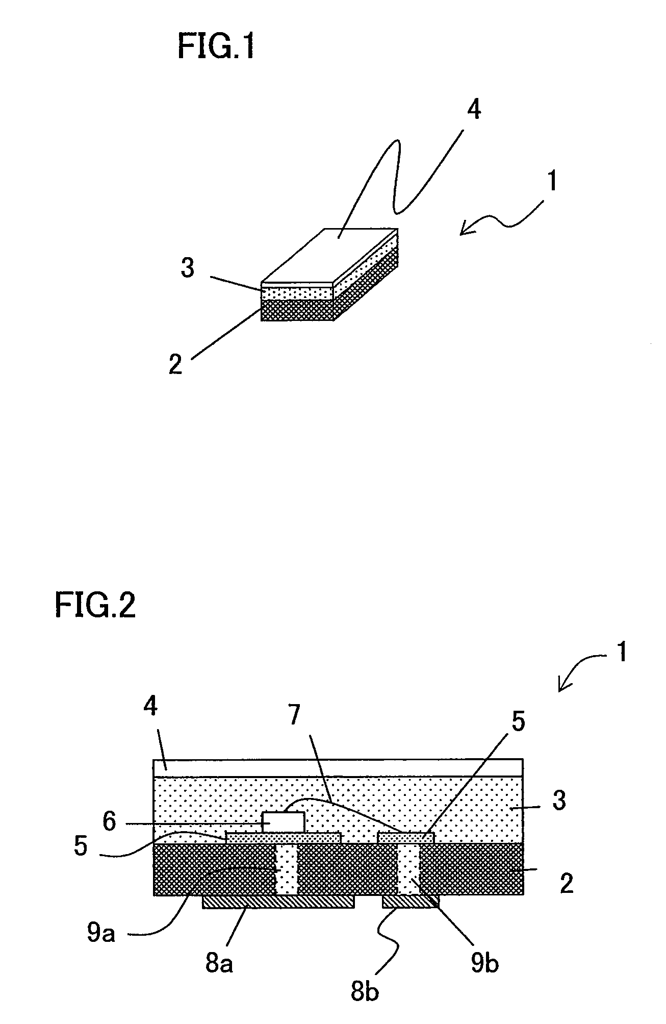
[0146]FIG. 9 is a longitudinal cross sectional view showing a light emitting apparatus according to Example 1 of Embodiment 3 of the present invention. Further, the same reference numerals are provided for those structural members which have the same functional effects as those in FIG. 2.

[0147]In FIG. 9, a light emitting apparatus 15 according to Example 1 has an encapsulating resin section 3, the encapsulating resin section being divided into a layer substantially including a phosphor 13 and a layer substantially including an optical diffusion material 14 as a surface resin layer from the side closer to an LED chip 6 as a light emitting device. Alternatively, the encapsulating resin section is divided into a layer substantially including the phosphor 13, an intermediate layer including the phosphor 13 and an optical diffusion material 14 intermingled together, and a layer substantially including the optical diffusion material 14 as the surface resin layer from the side closer to th...


PUM


Abstract

A light emitting apparatus is provided, and the light emitting apparatus has a light emitting device mounted on a substrate or a resin package where a substrate surface or the resin package is resin-encapsulated by an encapsulating resin section added with a phosphor in such a manner to cover the light emitting device. A surface resin layer of a different color from that of the encapsulating resin section is provided on a surface side of the encapsulating resin section.

Description

[0001]This Nonprovisional application claims priority under 35 U.S.C. §119(a) on Patent Application No. 2007-149815 filed in Japan on Jun. 5, 2007, the entire contents of which are hereby incorporated by reference.BACKGROUND OF THE INVENTION[0002]1. Field of the Invention[0003]The present invention relates to a light emitting apparatus equipped with a light emitting device, such as an LED, and resin-encapsulated thereon; a method for manufacturing the light emitting apparatus; an electronic device equipped with the light emitting apparatus as camera lighting therein, such as a digital camera (e.g., digital video camera and digital still camera), a door intercom camera, a camera for television telephone, and a camera equipped in a cell phone; and a cell phone device with the camera equipped in a cell phone.[0004]2. Description of the Related Art[0005]LEDs have been conventionally used as a flash for camera lighting of a cell phone device, and References 1 and 2, for example, disclose...

Claims


Application Information

Patent Timeline
Patent Type & Authority Applications(United States)
IPC IPC(8): H01J1/62H01J9/02
CPCC09K11/02C09K11/0883C09K11/7721C09K11/7734H01L33/46H01L33/50H01L2933/0091H01L2224/48091H01L2924/00014C09K11/77342
Inventor OHTA, MASAYUKIKONISHI, MASAHIROTAKENAKA, YASUJI
Owner SHARP KK
Why Eureka
Try Eureka