Radar apparatus

a technology of radar and apparatus, applied in direction finders, multi-channel direction-finding systems using radio waves, instruments, etc., can solve the problems of increasing the calculation amount, limiting the angular resolution, and unable to apply fft, so as to increase the aperture diameter, reduce the calculation amount, and enhance the angular resolution

Active Publication Date: 2008-12-11
MITSUBISHI ELECTRIC CORP
View PDF9 Cites 34 Cited by
  • Summary
  • Abstract
  • Description
  • Claims
  • Application Information

AI Technical Summary

Benefits of technology

[0016]The invention, having been conceived in order to solve the heretofore described kind of problem, has an object of providing a radar apparatus capa

Problems solved by technology

However, the angular resolution has a limitation under a constraint such as disposing the radar apparatus in a limited space.
However, as a CH disposition including the virtual CH's becomes unequally spaced depending o

Method used


Image

  • Radar apparatus
  • Radar apparatus
  • Radar apparatus

Examples


first embodiment

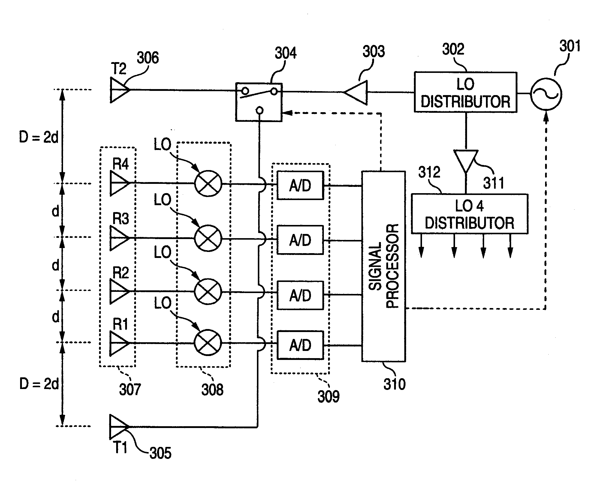
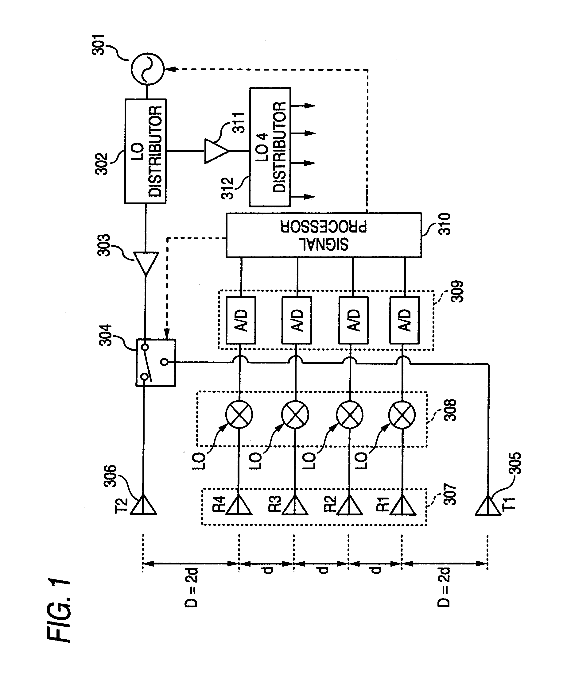
[0034]A description will be given of a first embodiment corresponding to the first aspect of the invention. FIG. 1 showing a radar apparatus according to the first embodiment, the radar apparatus includes a first transmitting antenna 305 (T1) and a second transmitting antenna 306 (T2), switched between by a transmitting switch 304. Receiving antennas 307, configured of a plurality (in the embodiment, four) of receiving antennas R1, R2, R3 and R4, are disposed between the first and second transmitting antennas 305 and 306 (T1 and T2). The receiving antennas R1 to R4 are disposed at regular spacings d. The transmitting antennas 305 (T1) and 306 (T2), positioned on either side of the receiving antennas R1 to R4, are spaced a spacing D=2d away from the respective adjacent receiving antennas R1 and R4 positioned on either end of the receiving antennas 307.

[0035]A connection is made in such a way that a signal generated by a voltage control oscillator (hereafter abbreviated as a VCO) 301 ...

second embodiment

[0063]A description will be given of a second embodiment corresponding to the second and third aspects of the invention. A configuration of a radar apparatus of the embodiment is the same as that of FIG. 1. Hereafter, a description will be given only of points differing from those of the first embodiment.

[0064]In any of the cases of the heretofore described beamformer method, which searches for the direction in which the received power of the antenna beam reaches its maximum after the DBF, monopulse method (using the amplitude or the phase), and super resolution method, which are the methods for the angle calculation, it is desirable that amplitude and phase characteristics of the plurality of receiving antennas are as uniform as possible. This is because, in the event that the amplitude characteristics of the receiving antennas differ from one another, a distortion occurs in the synthesis antenna pattern after the DBF and, in the beamformer method which searches for the direction i...


PUM


Abstract

A radar apparatus includes: a plurality of receiving antennas disposed at regular spacings; two transmitting antennas which are positioned each at opposed ends of the receiving antennas, and a spacing of which away from the receiving antennas adjacent thereto is a natural number multiple of half a disposition spacing of the plurality of the receiving antennas; and a signal processor which, after the two transmitting antennas transmit electric waves in time divisions, and then one for each of the plurality of receiving antennas receives waves reflected from a target, subjects the obtained received signals to a digital beam forming process, in which case the signal processor, after subjecting the received signals to a fast Fourier transform process in a time direction, carries out a fast Fourier transform process in a space direction.

Description

BACKGROUND OF THE INVENTION[0001]1. Technical Field[0002]The present invention relates to a radar apparatus which carries out a transmission and reception of an electric wave using a plurality of antennas.[0003]2. Related Art[0004]In general, in a radar apparatus, an angle of a target can be obtained by scanning an antenna beam narrowed down to a desired width. Scanning methods can be divided largely into mechanical scanning methods and electronic scanning methods and, as one electronic scanning method, there is a digital beam forming (hereafter abbreviated as a DBF).[0005]The DBF is a method in which an electric wave transmitted from a transmitting antenna and reflected off the target is received by a plurality of receiving antennas at one time, and various antenna patterns are formed by a digital signal processing, using the received signals. It is conceivable that, in a heretofore known phased array type antenna, a function of an analog phase shifter equipped on each antenna, and...

Claims


Application Information

Patent Timeline
IPC IPC(8): G01S13/00
CPCG01S3/32G01S3/48G01S3/74G01S7/03G01S13/34G01S13/42G01S13/44H01Q21/08H01Q21/22G01S13/345
Inventor MATSUOKA, KATSUJI
Owner MITSUBISHI ELECTRIC CORP
Why Eureka
Try Eureka