Display panel driving method, display apparatus, display panel driving apparatus and electronic apparatus

a technology of display panel and driving method, which is applied in the direction of instruments, diodes, computing, etc., can solve the problems of restricting the variation range of peak luminance level, and achieve the suppression of peak luminance, flickering and motion artifacts, and increase of movement width of line of sight upon display of moving images.

a technology of display panel and driving method, which is applied in the direction of instruments, diodes, computing, etc., can solve the problems of restricting the variation range of peak luminance level, and achieve the suppression of peak luminance, flickering and motion artifacts, and increase of movement width of line of sight upon display of moving images.

US20080303847A1Active Publication Date: 2008-12-11JOLED INC

Image

  • Display panel driving method, display apparatus, display panel driving apparatus and electronic apparatus
  • Display panel driving method, display apparatus, display panel driving apparatus and electronic apparatus
  • Display panel driving method, display apparatus, display panel driving apparatus and electronic apparatus

Examples


Embodiment Construction

[0091]In the following, an organic EL panel of the active matrix driving type to which embodiments according to the present invention are applied is described.

[0092]It is to be noted that, to those matters which are not disclosed in the present specification and the accompanying drawings, techniques which are known in the technical field to which an embodiment according to the present invention belongs are applied.

A. STRUCTURE OF THE ORGANIC EL PANEL

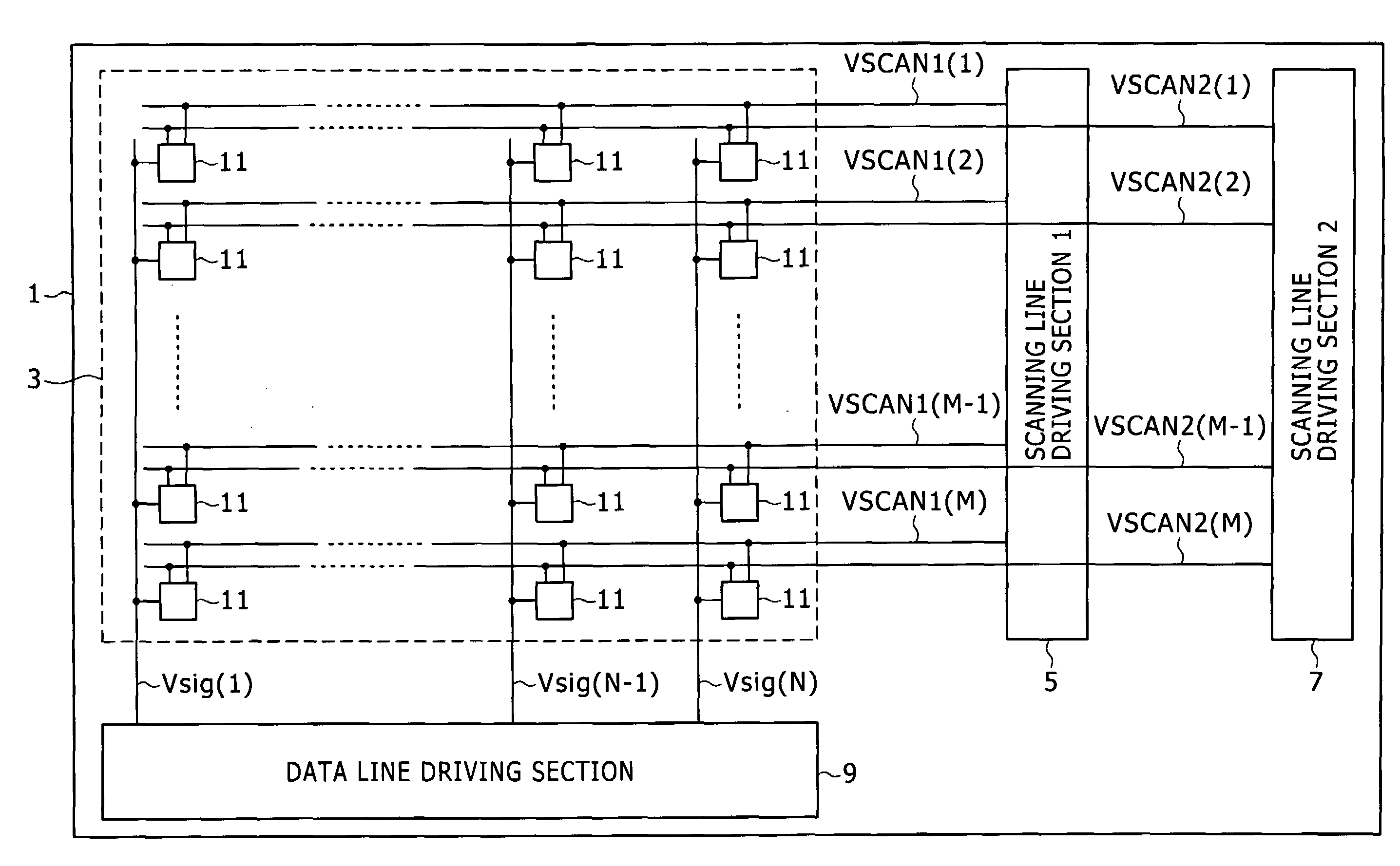
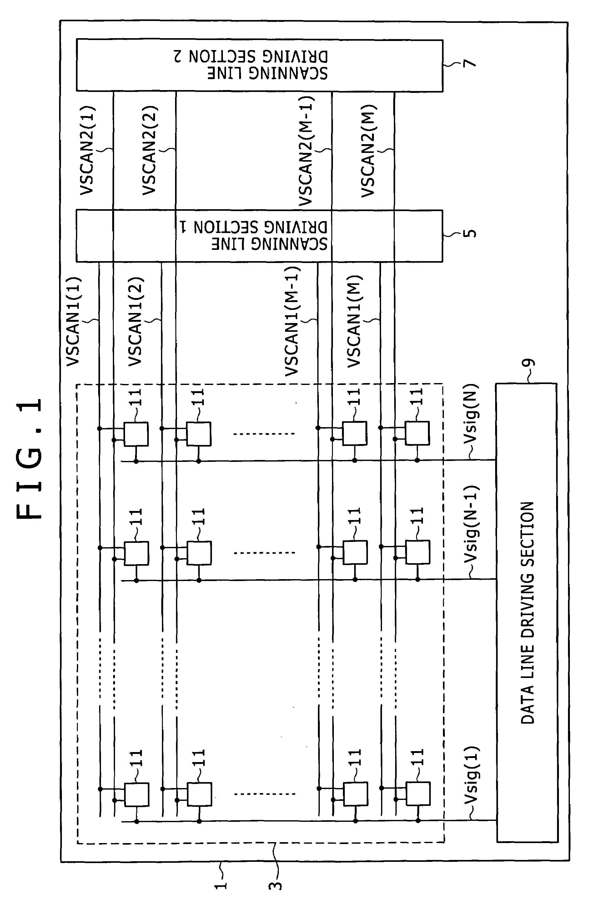
[0093]FIG. 17 shows an example of a general configuration of an organic EL panel to which an embodiment according to the present invention is applied.

[0094]Referring to FIG. 17, the organic EL panel 21 includes a pixel array section 3, a first scanning line driving section 5 for writing a signal voltage, a second scanning line driving section 7 for controlling the light emitting period, a data line driving section 9, and a light emitting timing determination section 23. The pixel array section 3 includes pixel circuits 11 arranged in M r...


PUM


Abstract

In the present invention, there is provided a display panel driving method of the type wherein the total light emitting period length within a one-field period is controlled to variably control the peak luminance level of a display panel, including the step of: variably controlling, where the one-field period has N light emitting periods, N being equal to or greater than 2, the end timing of the ith light emitting period and the start timing of the i+1th light emitting period so as to satisfy the total light emitting period length within the one-field period, i being an odd number which satisfies 1≦i≦N−1 while i+1 satisfies 2≦i+1≦N.

Description

CROSS REFERENCES TO RELATED APPLICATIONS[0001]The present invention contains subject matter related to Japanese Patent Application JP 2007-148697 filed in the Japan Patent Office on Jun. 5, 2007, and to Japanese Patent Application JP 2007-148698 filed in the Japan Patent Office on Jun. 5, 2007, the entire contents of which being incorporated herein by reference.BACKGROUND OF THE INVENTION[0002]1. Field of the Invention[0003]This invention relates generally to a method for controlling the peak luminance level of a display panel, and more specifically to a display panel driving method, a display apparatus, a display panel driving apparatus and an electronic apparatus.[0004]2. Description of the Related Art[0005]In recent years, development of display apparatus of the self-luminous type wherein organic EL (Electro Luminescence) devices are arranged in a matrix has been and is advancing. A display panel which uses an organic EL device is simple and easy in reduction in weight and film t...

Claims


Application Information

Patent Timeline
11 Dec 2008
Publication
US20080303847A1
IPC
G09G5/10; G09G3/30
CPC
G09G3/2029; G09G3/3225; G09G5/10; G09G2320/0261; G09G2320/064; G09G2320/0247; H01L27/0808; H01L29/66356
Inventors
ASANO, MITSURU