Light emitting device, surface light source device, and image display device

Active Publication Date: 2008-12-11
SATURN LICENSING LLC
View PDF15 Cites 5 Cited by
  • Summary
  • Abstract
  • Description
  • Claims
  • Application Information

AI Technical Summary

Benefits of technology

[0009]In the image display device of the side edge type in the related art, however, because the plurality of light emitting devices are arranged on peripheral sides of the light guiding plate, an amount of light at a distant part on the display p

Problems solved by technology

In the image display device of the side edge type in the related art, however, because the plurality of light emitting devices are arranged on peripheral sides of the light guiding plate, an amount of light at a distant part on the display panel from the light emitting devices may become insufficient.
It is therefore necessary to correspondingly increase the number of light emitting devices or use light emitting devices having high emission intensity, thus raising manufa

Method used


Image

  • Light emitting device, surface light source device, and image display device
  • Light emitting device, surface light source device, and image display device
  • Light emitting device, surface light source device, and image display device

Examples


Embodiment Construction

[0038]The best mode of a light emitting device, a surface light source device, and an image display device according to the present invention will hereinafter be described with reference to the accompanying drawings.

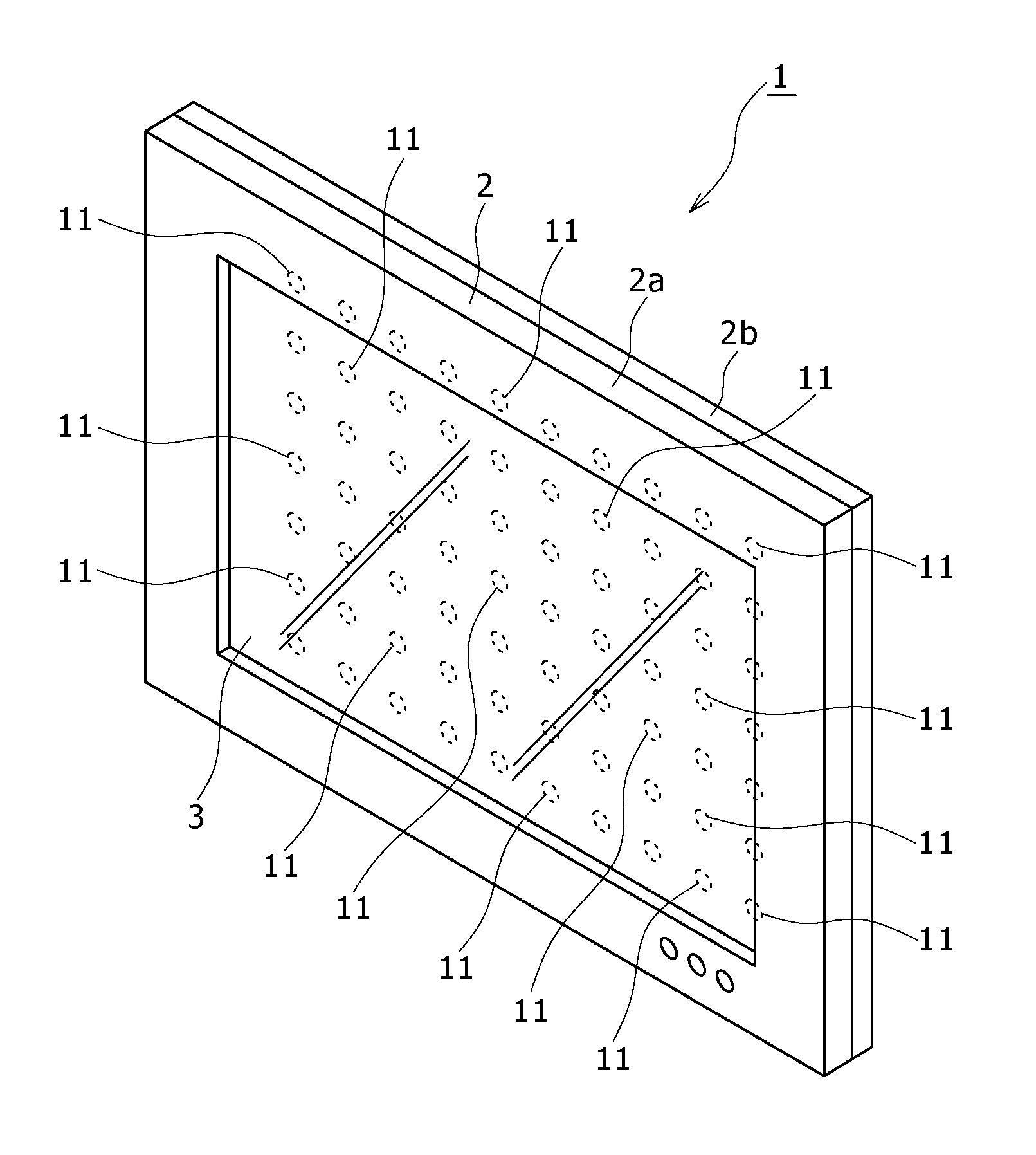
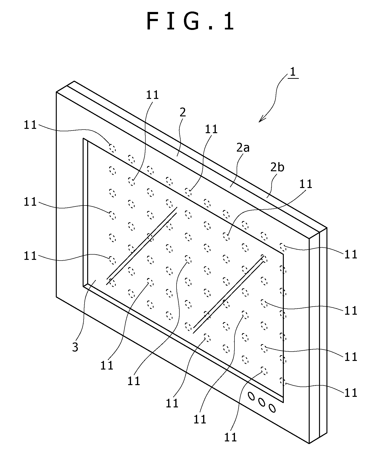
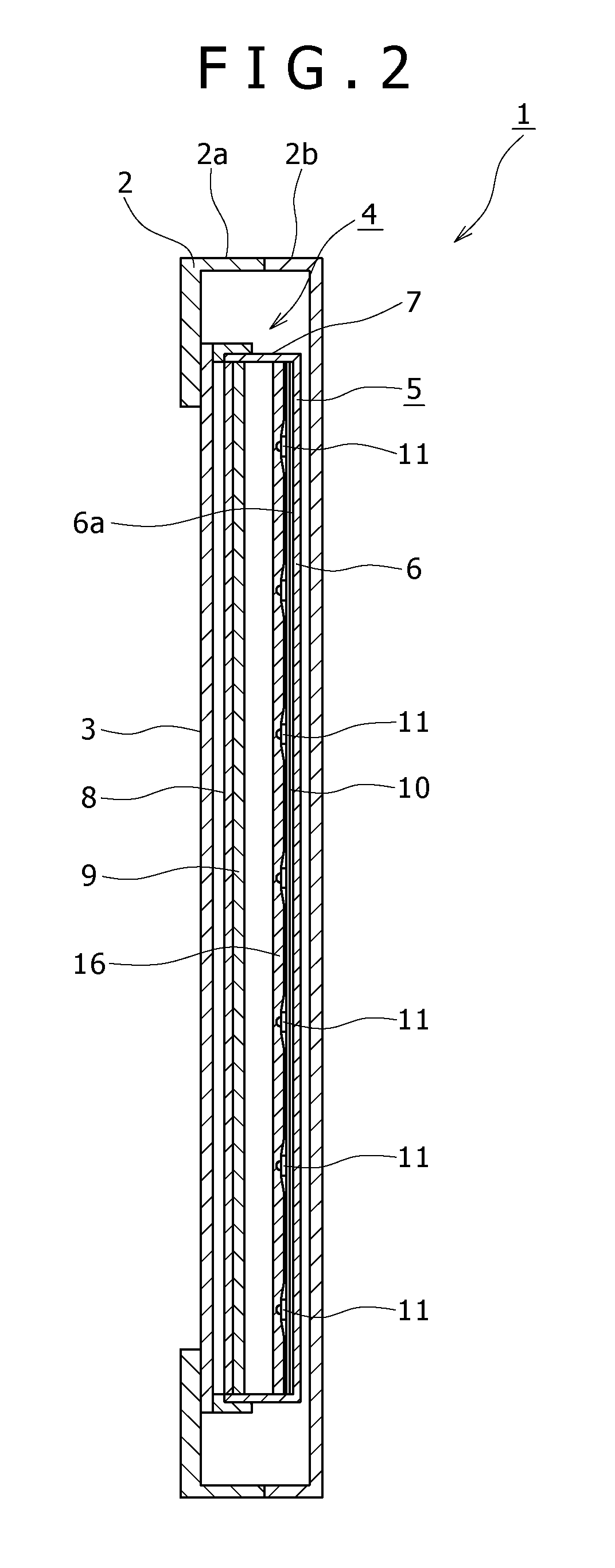
[0039]In the best mode illustrated below, an image display device according to an embodiment of the present invention is applied to a television receiver for displaying an image on a liquid crystal panel, a surface light source device according to an embodiment of the present invention is applied to a surface light source device used in the television receiver, and a light emitting device according to an embodiment of the present invention is applied to a light emitting device used in the surface light source device.

[0040]It is to be noted that the scope of application of the present invention is not limited to the television receiver having the liquid crystal panel, and the surface light source device and the light emitting device used in the television receiver, and th...


PUM


Abstract

A light emitting device includes a plurality of light emitting diodes, a plurality of sealing resins, and a lens body formed in substantially a shape of a flat plate for guiding the light. The lens body is also disposed in a state of extending over the disposition surface of each sealing resin. The lens body includes a plurality of lens parts and a plurality of light guiding parts for reflecting the light by inside surfaces of the light guiding parts. The plurality of lens parts and the plurality of light guiding parts of the lens body are formed integrally with each other. The lens parts are disposed on the respective disposition surfaces of the sealing resins, and a plurality of light emitting function parts for sending out the light reflected by the inside surfaces of the light guiding parts are formed in the light guiding parts.

Description

CROSS REFERENCES TO RELATED APPLICATIONS[0001]The present invention contains subject matter related to Japanese Patent Application JP 2007-150822 filed in the Japan Patent Office on Jun. 6, 2007, the entire contents of which being incorporated herein by reference.BACKGROUND OF THE INVENTION[0002]1. Field of the Invention[0003]The present invention relates to a technical field of a light emitting device, a surface light source device, and an image display device, and particularly to a technical field in which reduced thickness is achieved by providing a lens body obtained by forming lens parts and light guiding parts integrally with each other, and uniformity of luminance is achieved.[0004]2. Description of the Related Art[0005]There is a lighting device that performs lighting using a plurality of light emitting devices having a light emitting diode as a light source.[0006]Such a lighting device is, for example, used as lighting equipment using a light source for direct lighting or u...

Claims


Application Information

Patent Timeline
IPC IPC(8): F21V8/00H01L33/00H01L33/58
CPCG02B6/0018G02B6/0021G02B6/0038G02B6/0061G02F1/133603G02F1/133606
Inventor OHKAWA, SHINGOOKU, TAKASHINAKAKI, KENICHISHIBANUMA, TETSUO
Owner SATURN LICENSING LLC
Why Eureka
Try Eureka