Built-in swing mechanism of rotary fan

Active Publication Date: 2008-12-11
KING JIH ENTERPRISE CORP
View PDF4 Cites 36 Cited by
  • Summary
  • Abstract
  • Description
  • Claims
  • Application Information

AI Technical Summary

Benefits of technology

[0014]The present invention provides an innovative rotary fan with a built-in swing mechanism. With the help of a drive motor, the rotary fan along with the rotary vane will generate axially oblique circulating oscillation to change aut

Problems solved by technology

Since the vibration generated from the rotation of axle center could also drive the displacemen

Method used


Image

  • Built-in swing mechanism of rotary fan
  • Built-in swing mechanism of rotary fan
  • Built-in swing mechanism of rotary fan

Examples


Embodiment Construction

[0028]The features and the advantages of the present invention will be more readily understood upon a thoughtful deliberation of the following detailed description of a preferred embodiment of the present invention with reference to the accompanying drawings.

[0029]FIGS. 1-4 depict preferred embodiments of the built-in swing mechanism of rotary fan of the present invention. The embodiments are provided only for explanatory purposes with respect to the patent claims.

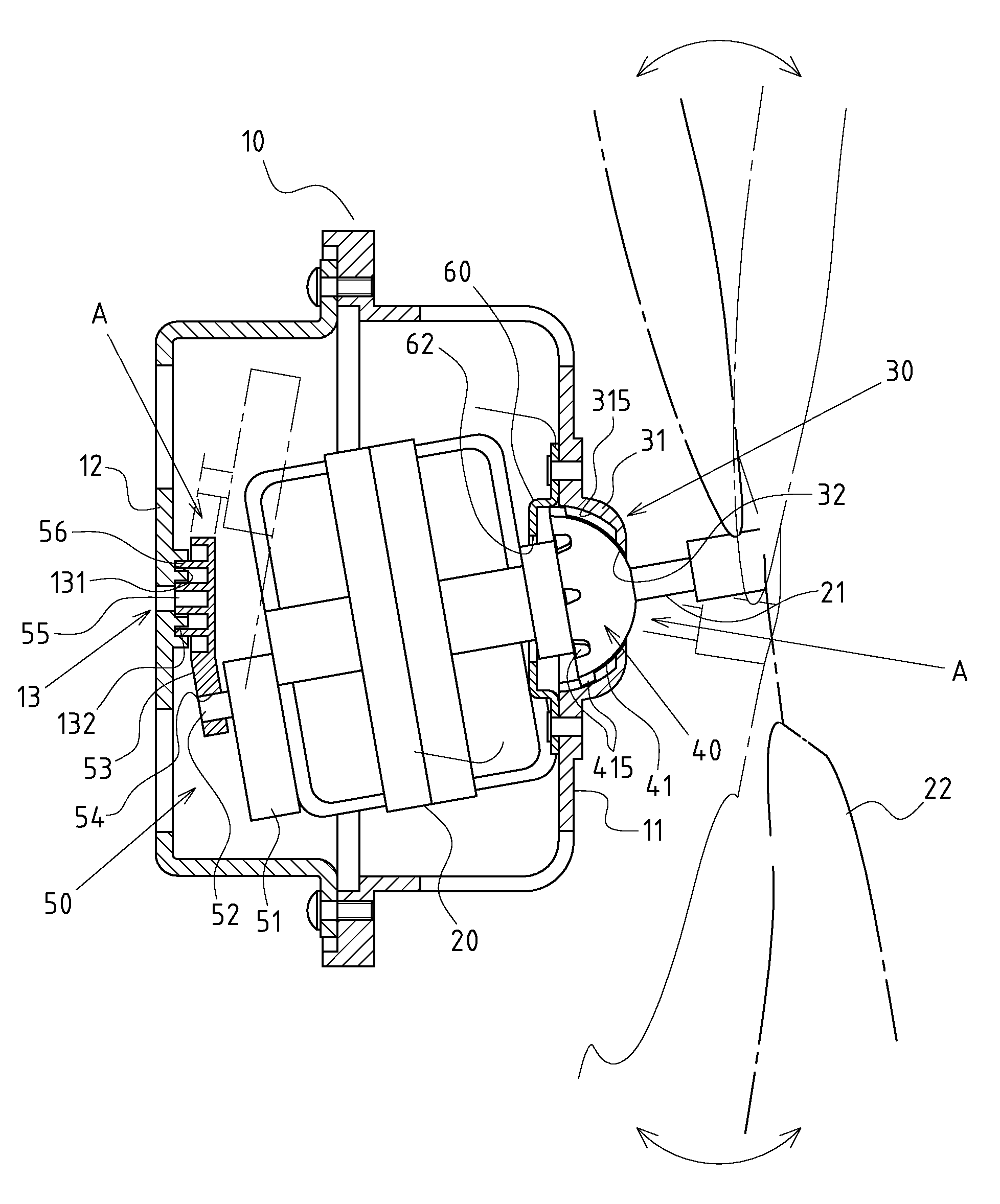
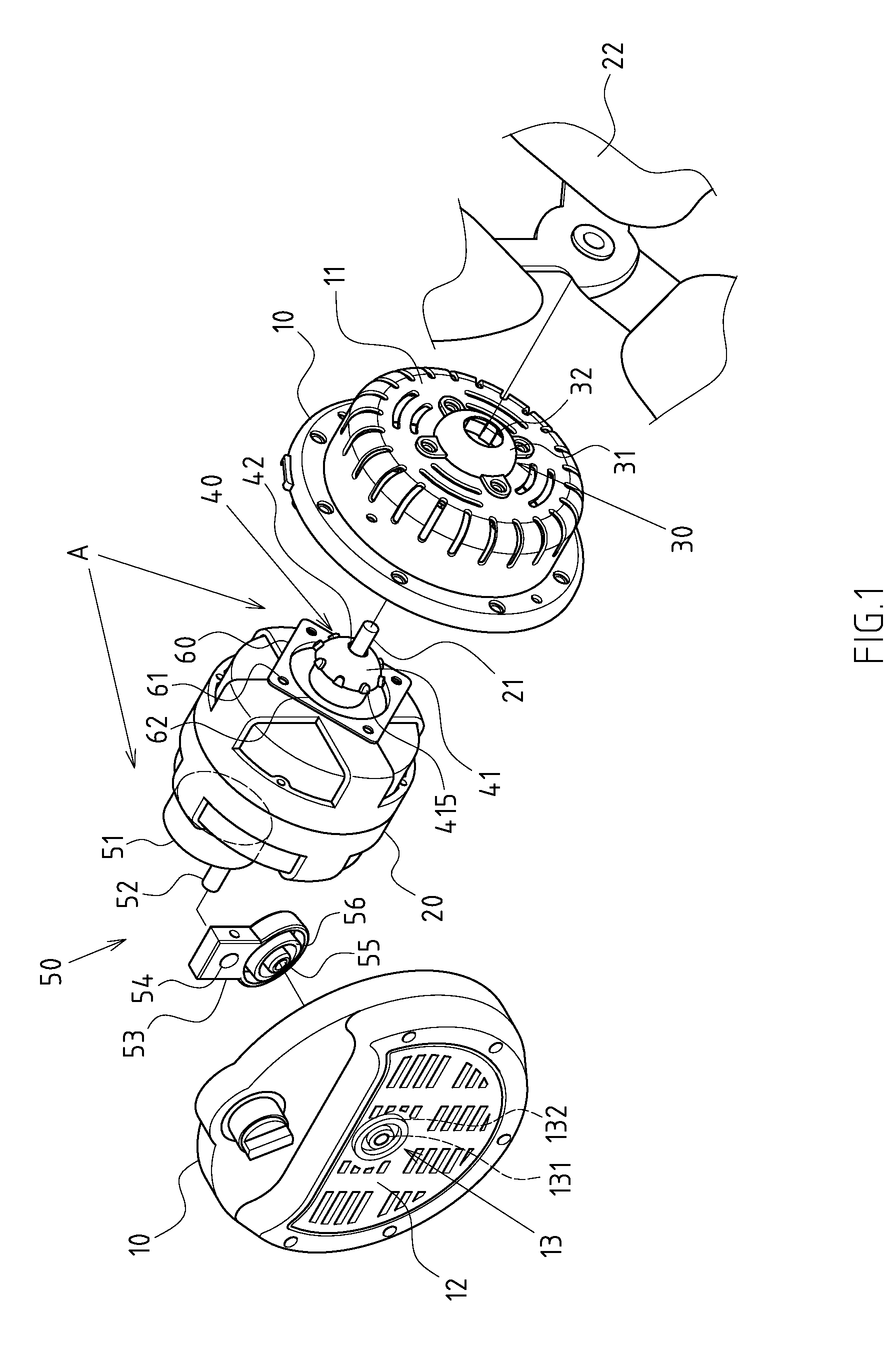
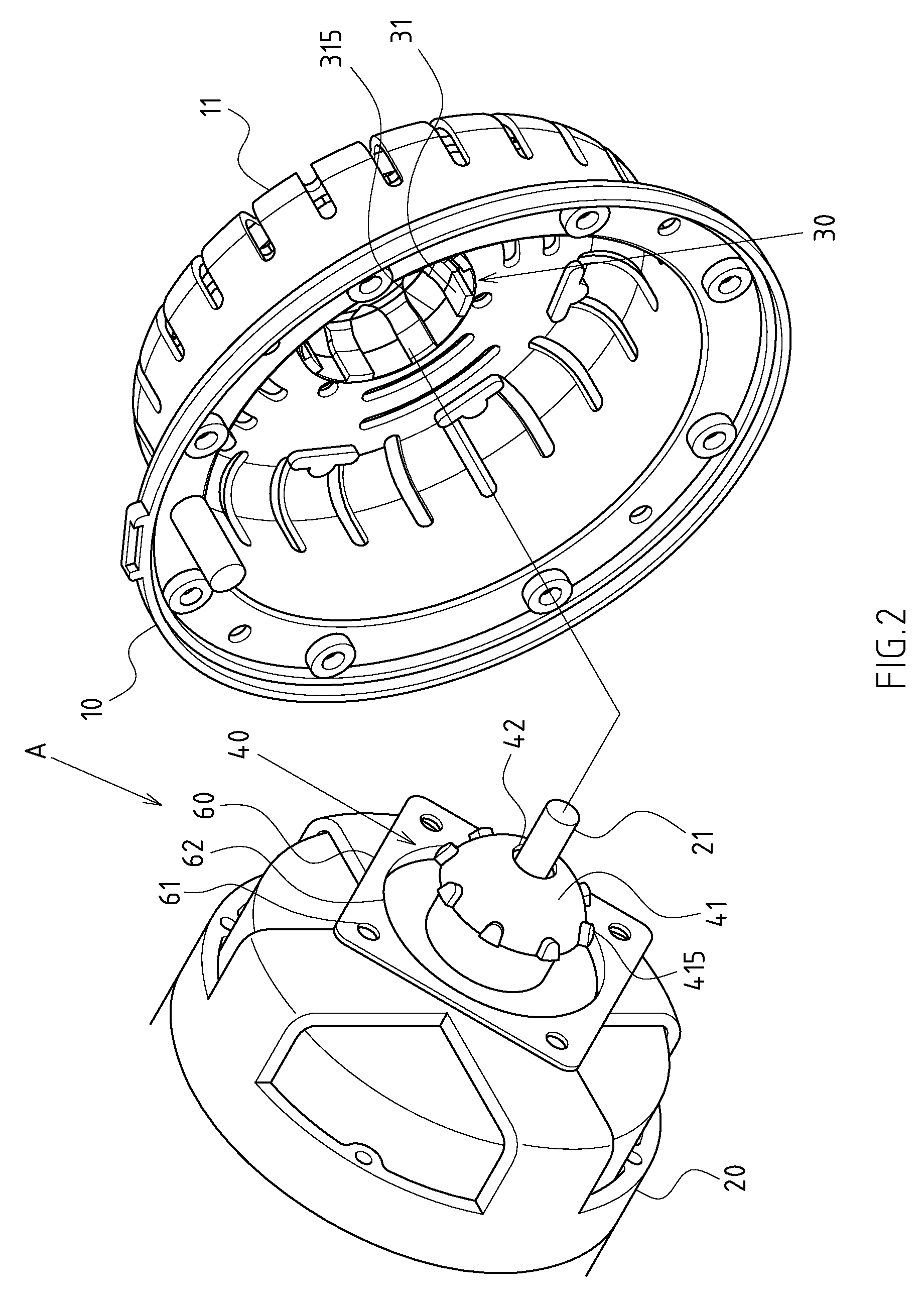
[0030]The built-in swing mechanism A is placed within the main casing 10 of a rotary fan B, so that the axle center 21 of drive motor 20 along with the rotary vane 22 is driven to generate axially oblique circulating oscillation.

[0031]This built-in swing mechanism A includes a ball-and-socket support frame 30, arranged onto front wall 11 of the main casing 10 correspondingly to the axle center 21 of drive motor 20. The ball-and-socket support frame 30 is provided with a spherical supporting surface 31, and a through-hole 3...


PUM


Abstract

The present invention provides an improved built-in swing mechanism of a rotary fan. The mechanism includes a ball-and-socket support frame, arranged onto front wall of the main casing corresponding to the axle center of a drive motor and provided with a spherical supporting surface and a through-hole. A spherical abut seat is fastened at a front end of the drive motor is provided with a spherical abut surface that couples with the spherical supporting surface. A punch hole is placed at the center of spherical abut surface for the penetration of the axle center. A crank linkage element is assembled between rear end of the drive motor and the rear wall of the main casing. The first end of the crank linkage element can be driven to enable the oscillation of the second end. The second end is assembled at a rotary pivot corresponding to the main casing.

Description

CROSS-REFERENCE TO RELATED U.S. APPLICATIONS[0001]The present application is a continuation-in-part application under 35 U.S.C. § 120 of U.S. Ser. No. 11 / 759,842, filed on 7 Jun. 2007 and entitled “CONCEALED ROTARY FAN”.STATEMENT REGARDING FEDERALLY SPONSORED RESEARCH OR DEVELOPMENT[0002]Not applicable.NAMES OF PARTIES TO A JOINT RESEARCH AGREEMENT[0003]Not applicable.REFERENCE TO AN APPENDIX SUBMITTED ON COMPACT DISC[0004]Not applicable.BACKGROUND OF THE INVENTION[0005]1. Field of the Invention[0006]The present invention relates generally to a rotary fan, and more particularly to an innovative rotary fan with a built-in swing mechanism.[0007]2. Description of Related Art Including Information Disclosed Under 37 CFR 1.97 and 37 CFR 1.98[0008]The rotary fan of the present invention refers to a fan that feeds wind through the rotation of a rotary fan.[0009]The currently available rotary fan generally comprises oscillating and cover-rotating types from the angle of wind control. While ...

Claims


Application Information

Patent Timeline
IPC IPC(8): F01D7/00F04D29/36
CPCF04D25/105F05B2240/202
Inventor FU, CHIAO
Owner KING JIH ENTERPRISE CORP
Why Eureka
Try Eureka