
Mechanically detachable vaso-occlusive device

a vaso-occlusive device and mechanical detachment technology, applied in the field of vaso-occlusive device implanting systems and delivery devices, can solve the problems of time lag, inability to elapse in electrolysis, and inability to fully discharge, and achieve the effect of eliminating frictional pinching of the filamen

Active Publication Date: 2008-12-11
BOSTON SCI SCIMED INC
View PDF29 Cites 85 Cited by
  • Summary
  • Abstract
  • Description
  • Claims
  • Application Information

AI Technical Summary

Benefits of technology

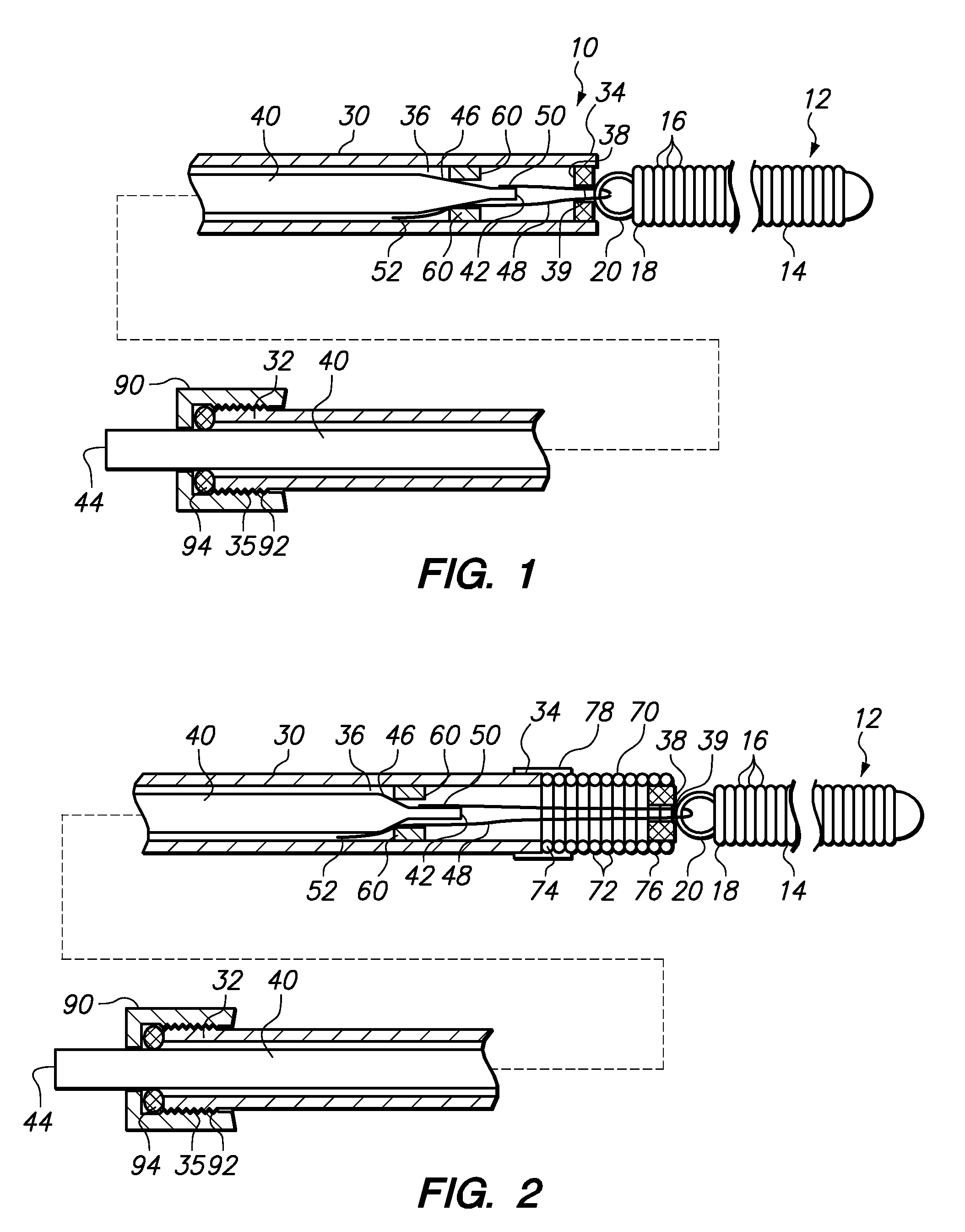
[0015]A blocking member may be disposed on the distal end of the elongate pusher member. The blocking member includes an aperture or passageway dimensioned to permit passage of the filament but not the coil. The blocking member thus prevents the coil from being retracted into the elongate pusher member.
[0016]Optionally, the elongate pusher member may include a coil member disposed on a distal end thereof. The coil member imparts added flexibility to the distal region of the elongate pusher member.
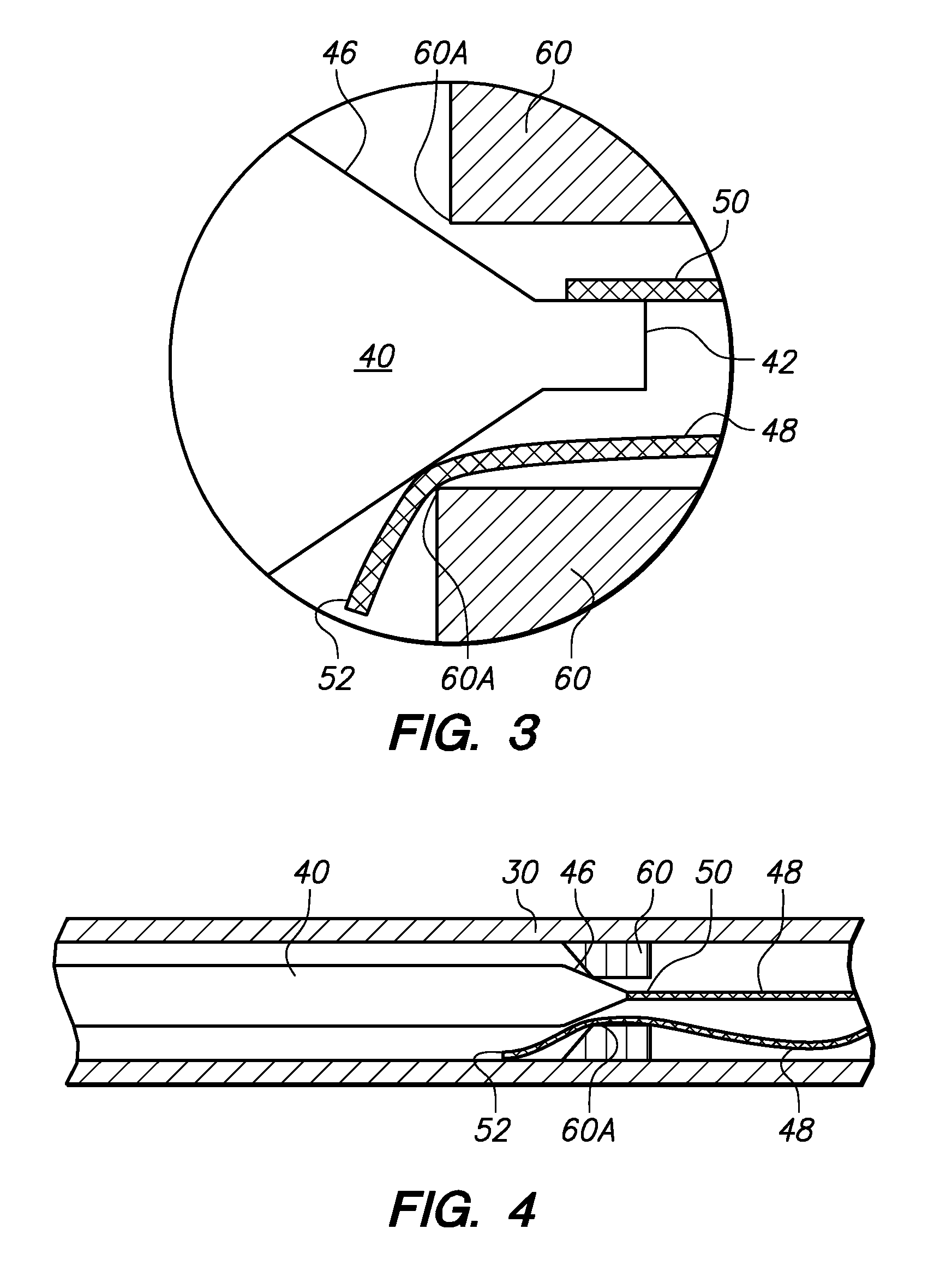
[0018]In still another aspect of the invention, a method of making a vaso-occlusive coil includes the steps of loading a vaso-occlusive coil on a distal end of the elongate pusher member by passing a filament coupled to an elongate releasing member through a securing member of the vaso-occlusive coil. The vaso-occlusive coil is then locked to the elongate pusher member by advancing the elongate releasing member distally within the elongate pusher member so as wedge or pinch the filament between the elongate releasing member and a locking surface of the elongate pusher member. For deployment, the vaso-occlusive coil is then positioned adjacent to a deployment site such as, for instance, an aneurysm. The coil may be positioned by using a delivery catheter such as, for instance, a microcatheter. The coil is then released by retracting the elongate releasing member proximally relative to the elongate pusher member. Proximal retraction of the elongate releasing member eliminates the frictional pinching of the filament between the locking surface and the elongate releasing member. The filament can then be withdrawn proximally (in response to movement of the elongate releasing member) to de-couple from the securing member of the coil.

Problems solved by technology

An electrolytically severable junction is susceptible to electrolysis and disintegrates when the pusher wire is electrically charged in the presence of an ionic solution, such as blood or other bodily fluids.
One perceived disadvantage with vaso-occlusive devices that are deployed using electrolytic detachment is that the electrolytic process requires a certain amount of time to elapse to effectuate release of the vaso-occlusive element.
This time lag is also a perceived disadvantage for vaso-occlusive delivery devices that utilize thermal detachment mechanisms.
One problem with certain existing mechanical detachment systems is that the junction between the embolic element and the releasing member moves during the detachment process which may adversely impact the placement of the embolic element within the aneurysm.
Another complication is that mechanical detachment systems tend to have a stiff main section that complicates accurate placement of the delivery system at the desired location.
Mechanical detachment systems also are perceived by physicians as being harder to use than other devices.
In addition, certain mechanical detachment systems may jeopardize the integrity of the embolic element (e.g. coil) after detachment.

Method used


Image

  • Mechanically detachable vaso-occlusive device
  • Mechanically detachable vaso-occlusive device
  • Mechanically detachable vaso-occlusive device

Examples


Embodiment Construction

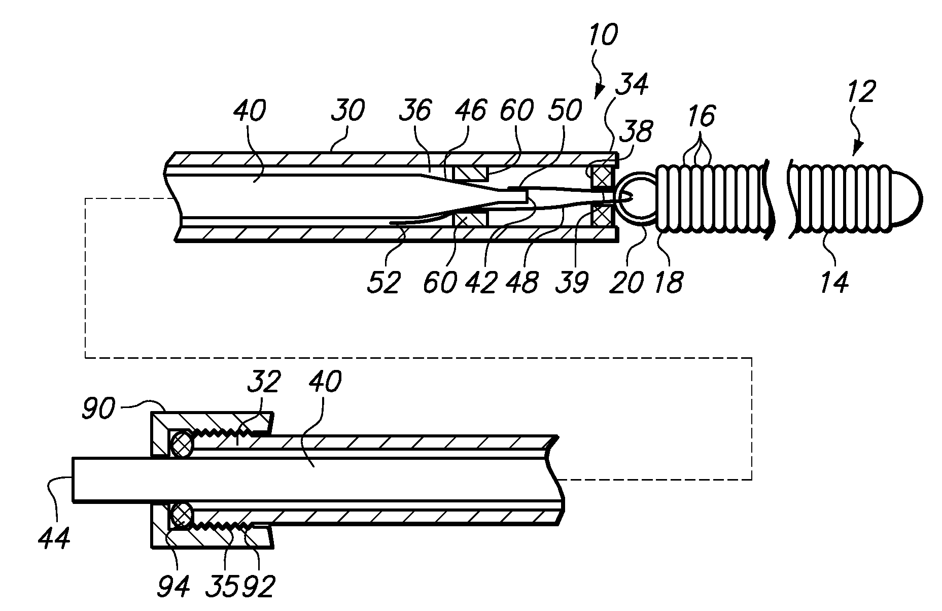
[0027]FIG. 1 illustrates a device 10 for delivering an occlusive element 12 to a vascular space such as, for example, aneurysm 100 (shown in FIG. 5). The occlusive element 12 may be formed as a vaso-occlusive coil 14 created from a plurality of coil windings 16. When manufacturing the vaso-occlusive coil 14, the coil material is wound into a coil shape, which will typically be linear. Generally speaking, the coil 14 is a metallic coil made from a platinum alloy or a super-elastic alloy such as titanium / nickel alloy, known as NITINOL. The diameter of the wire used in the production of the coils 14 may fall in the range of about 0.00025 inches to about 0.006 inches. The coil 14 may have a primary diameter of between about 0.003 and about 0.025 inches, but for most neurovascular applications, a diameter between about 0.008 to about 0.018 inches provides sufficient hoop strength to hold the coil 14 in place within the chosen body site, lumen, or cavity, without substantially distending ...


PUM

PropertyMeasurementUnit
Flexibilityaaaaaaaaaa
Stiffnessaaaaaaaaaa

Abstract

A device for delivering an occlusive element includes an elongate pusher member having a lumen. A locking member is disposed within the lumen of the elongate pusher member. A moveable elongate releasing member is disposed within the lumen of the elongate pusher member. A filament is secured to the distal end of the elongate releasing member. The occlusive member is locked to the elongate releasing member when the filament passes through a securing member on the occlusive member and is pinched or wedged between the locking member and the elongate releasing member. The occlusive element is in an unlocked state when the elongate releasing member is retracted proximally relative to the elongate pusher member. The filament, along with the elongate releasing member, are retracted proximally until the filament is detached or uncoupled from the securing member of the occlusive member.

Description

RELATED APPLICATION DATA[0001]The present application claims the benefit under 35 U.S.C. § 119 to U.S. provisional patent application Ser. No. 60 / 866,590, filed Nov. 20, 2006. The foregoing application is hereby incorporated by reference into the present application in its entirety.FIELD OF THE INVENTION[0002]The field of the invention generally relates to systems and delivery devices for implanting vaso-occlusive devices for establishing an embolus or vascular occlusion in a vessel of a human or veterinary patient.BACKGROUND OF THE INVENTION[0003]Vaso-occlusive devices or implants are used for a wide variety of reasons, including treatment of intra-vascular aneurysms. A common vaso-occlusive device takes the form of a soft, helically wound coil formed by winding a platinum (or platinum alloy) wire strand about a primary mandrel. The relative stiffness of the coil will depend, among other things, on its composition, the diameter of the wire strand, the diameter of the primary mandre...

Claims


Application Information

Patent Timeline
IPC IPC(8): A61B17/00
CPCA61B17/12113A61B17/12145A61B2017/12054A61B2017/12095Y10T29/49826A61B17/12022A61B17/12109A61B17/1214A61B2017/0053A61B2017/1205
Inventor WIN, THAZINQUE, LIKECHANG, ESTHERHUANG, ANN
Owner BOSTON SCI SCIMED INC
Learn More