
Multi-Modal Push Planner for Humanoid Robots

a humanoid robot and multi-modal technology, applied in the field of robot multi-modal push planner, can solve the problems of ineffective single-mode planning algorithms, inability to produce effective transition configurations, and inability to achieve effective transition configurations. to achieve the target configuration,

Active Publication Date: 2008-12-11
HONDA MOTOR CO LTD
View PDF22 Cites 33 Cited by
  • Summary
  • Abstract
  • Description
  • Claims
  • Application Information

AI Technical Summary

Benefits of technology

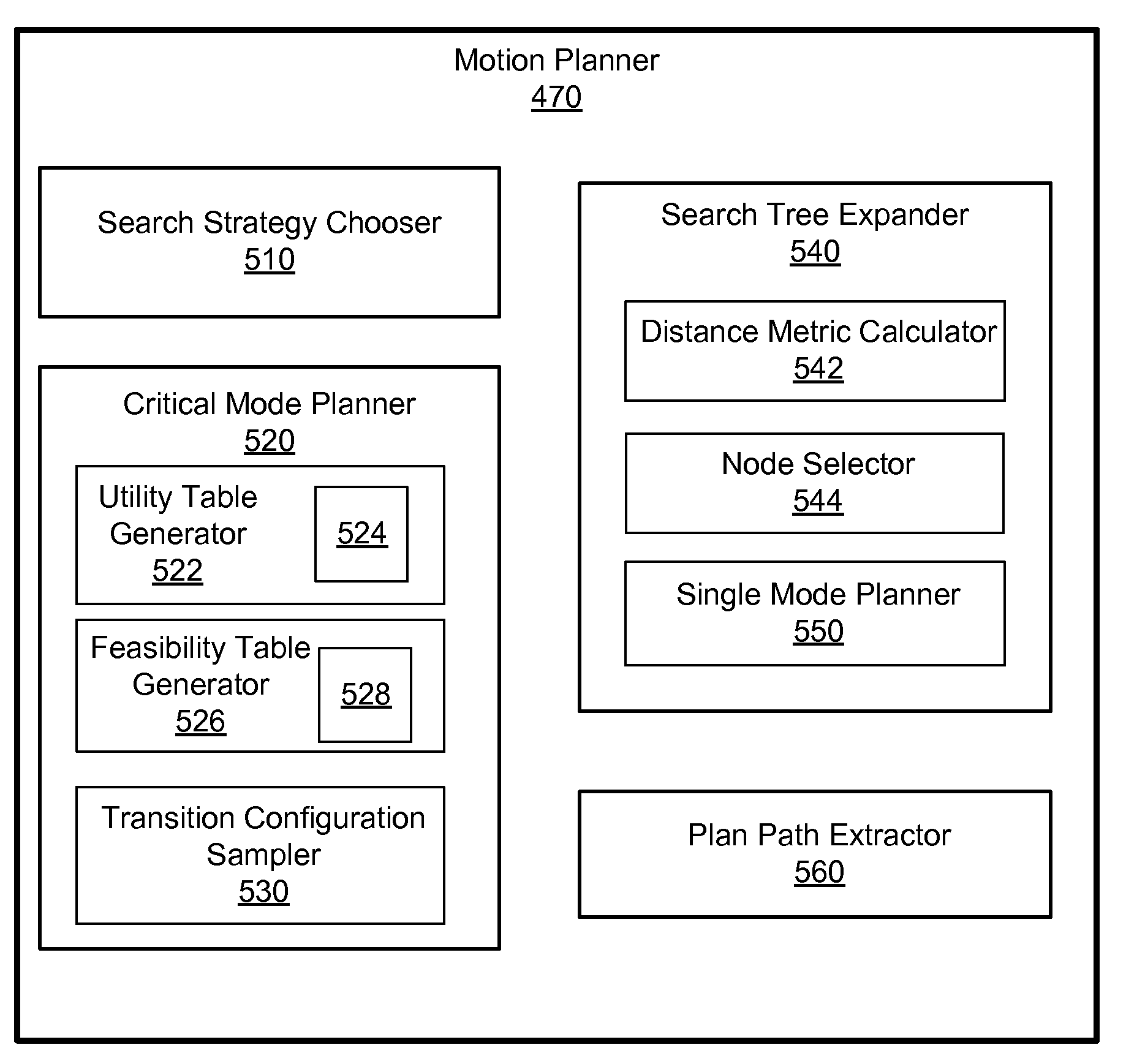
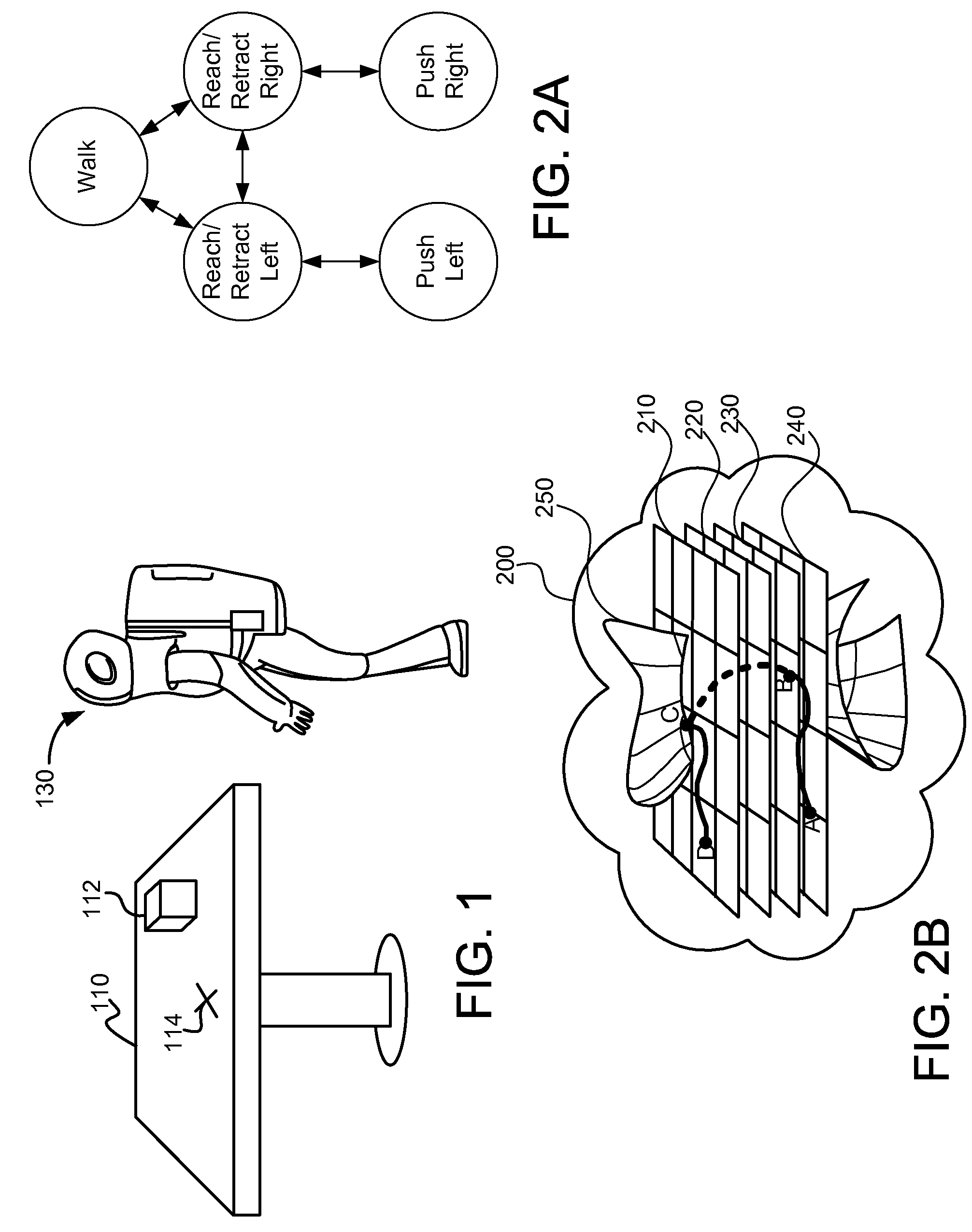
The present invention provides a method, system, and computer readable storage medium for planning motions for a subject device (e.g., a humanoid robot) operable in two or more modes (e.g., walk, reach / retract and push). Each mode has a set of constraints that must be followed by the subject device. The invention allows for the selection of a first transition configuration from a set of shared transition configurations and a nearby mode, and the search for a path from the first transition configuration to the target configuration. The invention also generates a tree to represent the possible configurations and calculates distances between nodes in the tree to determine feasibility and utility of transition configurations. The technical effects of the invention include improved planning and control of motions for humanoid robots, allowing for more efficient and effective movement in various modes.

Problems solved by technology

Algorithms for planning single-mode motions may not be suitable for planning multi-modal operations.
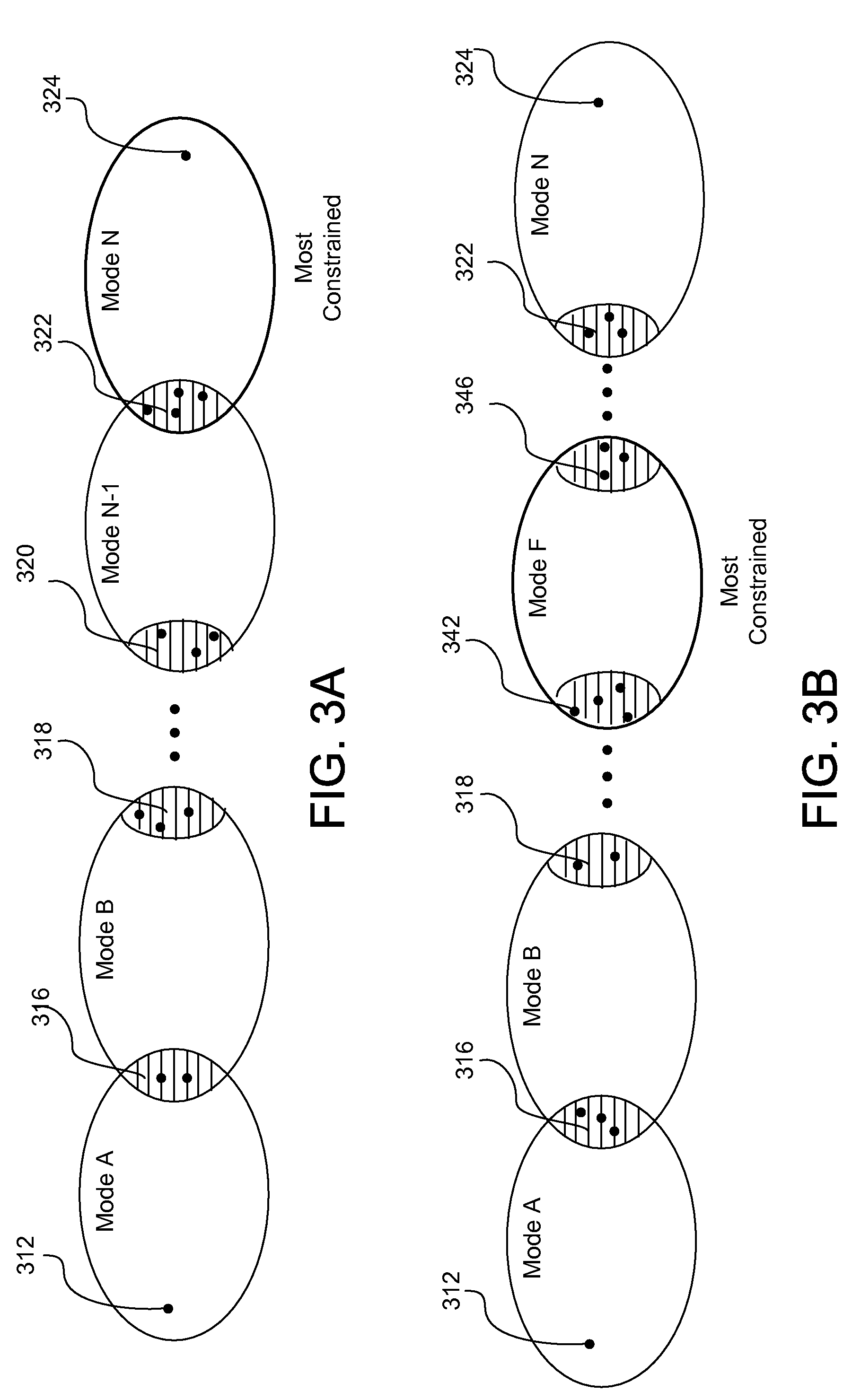
Conventional single-mode planning methods, however, are not effective in producing effective transition configurations.
If the discretization of the transition configurations is too sparse, transition configurations leading to the target configuration may be missed.
Conversely, if the discretization is too dense, excessive resources may be needed to conduct searches for the path of configurations.
Further, some pushes may be irreversible because of limited reach of the manipulators and other constraints on the configuration of the robots or devices.

Method used


Image

  • Multi-Modal Push Planner for Humanoid Robots
  • Multi-Modal Push Planner for Humanoid Robots
  • Multi-Modal Push Planner for Humanoid Robots

Examples


Embodiment Construction

[0023]A preferred embodiment of the present invention is now described with reference to the figures where like reference numbers indicate identical or functionally similar elements.

[0024]Reference in the specification to “one embodiment” or to “an embodiment” means that a particular feature, structure, or characteristic described in connection with the embodiments is included in at least one embodiment of the invention. The appearances of the phrase “in one embodiment” in various places in the specification are not necessarily all referring to the same embodiment.

[0025]Some portions of the detailed description that follows are presented in terms of algorithms and symbolic representations of operations on data bits within a computer memory. These algorithmic descriptions and representations are the means used by those skilled in the data processing arts to most effectively convey the substance of their work to others skilled in the art. An algorithm is here, and generally, conceived...


PUM


Abstract

Multi-modal planning method and system that search a path for the most constrained mode first, and then expands the searches for path in a less constrained mode. By searching the path for the most constrained mode first, less resource are wasted on searching for paths that does not result in a feasible path in the most constrained mode. Multi-modal planning is performed by precomputing feasibility and utility of transition configurations of two adjacent modes. The feasibility is used to exclude non-feasible transition configurations in the most constrained mode from being sampled. The utility is used to bias sampling of the transition configuration so that transition configurations with higher utility are sampled with higher probability. Paths of configurations with higher utility and efficiency are obtained by biasing the sampling of the transition configurations.

Description

CROSS-REFERENCE TO RELATED APPLICATIONS[0001]This application claims priority under 35 U.S.C. §119(e) to co-pending U.S. Provisional Patent Application No. 60 / 933,909 entitled “Multi-Modal Motion Planning For A Humanoid Robot Manipulation Task,” filed on Jun. 8, 2007, the subject matter of which is incorporated by reference herein in its entirety.FIELD OF THE INVENTION[0002]The present invention is related to a method and system for planning motions in a robot, more specifically to a method and system for planning motions involving multiple modes where each mode is subject to different constraints.BACKGROUND OF THE INVENTION[0003]In order to accomplish a certain task, robots or other devices may need to perform operations in multiple modes. One mode (for example, walking) may impose one set of constraints on the configuration of the robot while another mode (for example, pushing) may impose another set of constraints on the configuration of the robot. Such multi-modal planning is fo...

Claims


Application Information

Patent Timeline
Patent Type & Authority Applications(United States)
IPC IPC(8): B25J11/00
CPCB25J9/1664
Inventor NG-THOW-HING, VICTORHAUSER, KRISGONZALEZ-BANOS, HECTOR
Owner HONDA MOTOR CO LTD
Learn More