
Tracking and Handling of Super-Hot Data in Non-Volatile Memory Systems

a non-volatile memory and super-hot data technology, applied in the direction of memory adressing/allocation/relocation, instruments, computing, etc., can solve the problems of unsuitable mobile and handheld environment, bulky disk drives, and easy mechanical failures

Active Publication Date: 2013-01-24
SANDISK TECH LLC
View PDF2 Cites 98 Cited by
  • Summary
  • Abstract
  • Description
  • Claims
  • Application Information

AI Technical Summary

Benefits of technology

The patent is about a method for operating on data in a non-volatile memory system. The method involves identifying a set of data that is more likely to be rewritten in the future due to garbage collection, and then maintaining a smaller subset of that data in a separate portion of the memory. The technical effect of this method is to improve the efficiency and performance of the memory system by optimizing the use of memory cells and reducing the likelihood of data rewrites in the future.

Problems solved by technology

Conventional mass storage, based on rotating magnetic medium such as hard drives and floppy disks, is unsuitable for the mobile and handheld environment.
This is because disk drives tend to be bulky, are prone to mechanical failure and have high latency and high power requirements.
These undesirable attributes make disk-based storage impractical in most mobile and portable applications.
Obviously, the more bits a memory cell is configured to store, the smaller is the margin of error it has to operate in.
First, existing data stored in the flash memory cannot be updated by simply being overwritten.
When a page of data is updated by having the updated page written to a new location, the superseded page is rendered invalid and obsolete and becomes garbage cluttering the storage and will eventually be cleaned out to free up the space it is occupying.
Managing the updates and discarding the invalid ones are complicated by the block structure of flash memory.
This means the block will contain many garbage data taking up space.
However, the block can only be erased as a unit and so before the garbage data can be erased with the block, the valid data in the block must first be salvaged and copied into another block.
The larger the block, the more time is required for the garbage collection.
This obviously will degrade the write speed.
Generally, when subject to updates, some of the orderly blocks will contain obsolete data and keeping track of them will also consume part of the resource.
However, the block management system implementing logical groups will begin to be less optimized if the host writes mostly short and non-sequential data.
However, with constant use and frequent updates, the predetermined resource for page tracking will eventually be exhausted.
Also a large block and short and non-sequential data will cause the logical group in the block to contain invalid data more frequently and consume page addressing resource faster and therefore cause relocation to take place more frequently.
The problem with the large block size cannot be easily solved by simply reducing the block size as the block size tend to increase geometrically with each new generation of memory technology.
Thus, there is a great mismatch in the addressing granularity of a logical group corresponding to a block and a page.
In the case of short random writes into a large block, the block becomes non-ideal very quickly and eventually will need relocation.
This amounts to inefficient writes since the same page may have to be written and then re-copied one or more times (also referred to as “write amplification”.)
In practice, it will require more system resources and a relative large RAM to work with the memory controller.
This is insufficient for systems using a page addressing scheme and additional external RAM chips will be required.
The additional pinouts and interface circuits to support external RAM chips would add significantly to the cost.
Another problem with addressing granularity having very small units, such as 4 kB, is that it creates fragmented data, which is scattered between the blocks so much that maximum parallelism during read and data copy (due to update) is not achievable.

Method used


Image

  • Tracking and Handling of Super-Hot Data in Non-Volatile Memory Systems
  • Tracking and Handling of Super-Hot Data in Non-Volatile Memory Systems
  • Tracking and Handling of Super-Hot Data in Non-Volatile Memory Systems

Examples


Embodiment Construction

Memory System

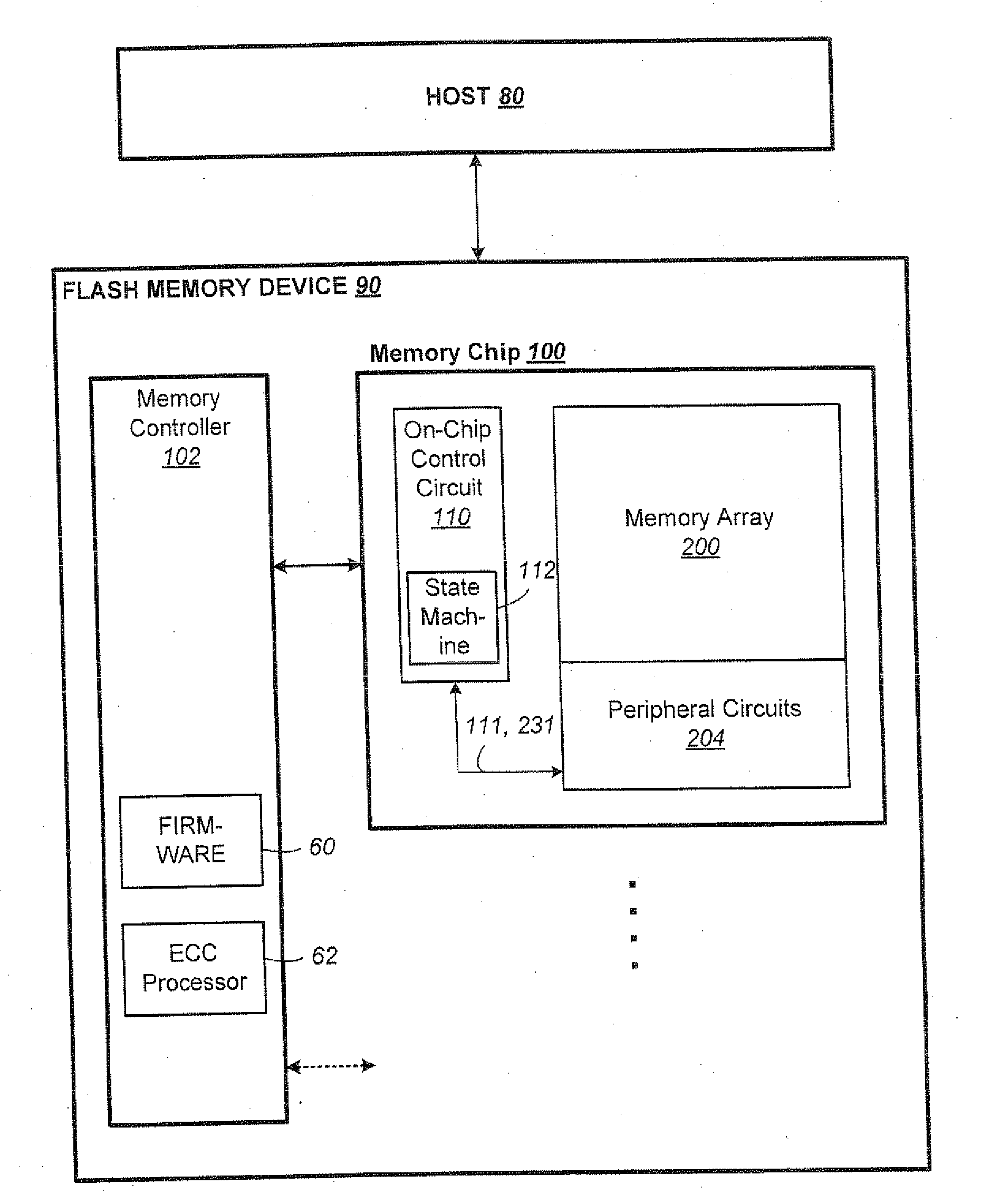
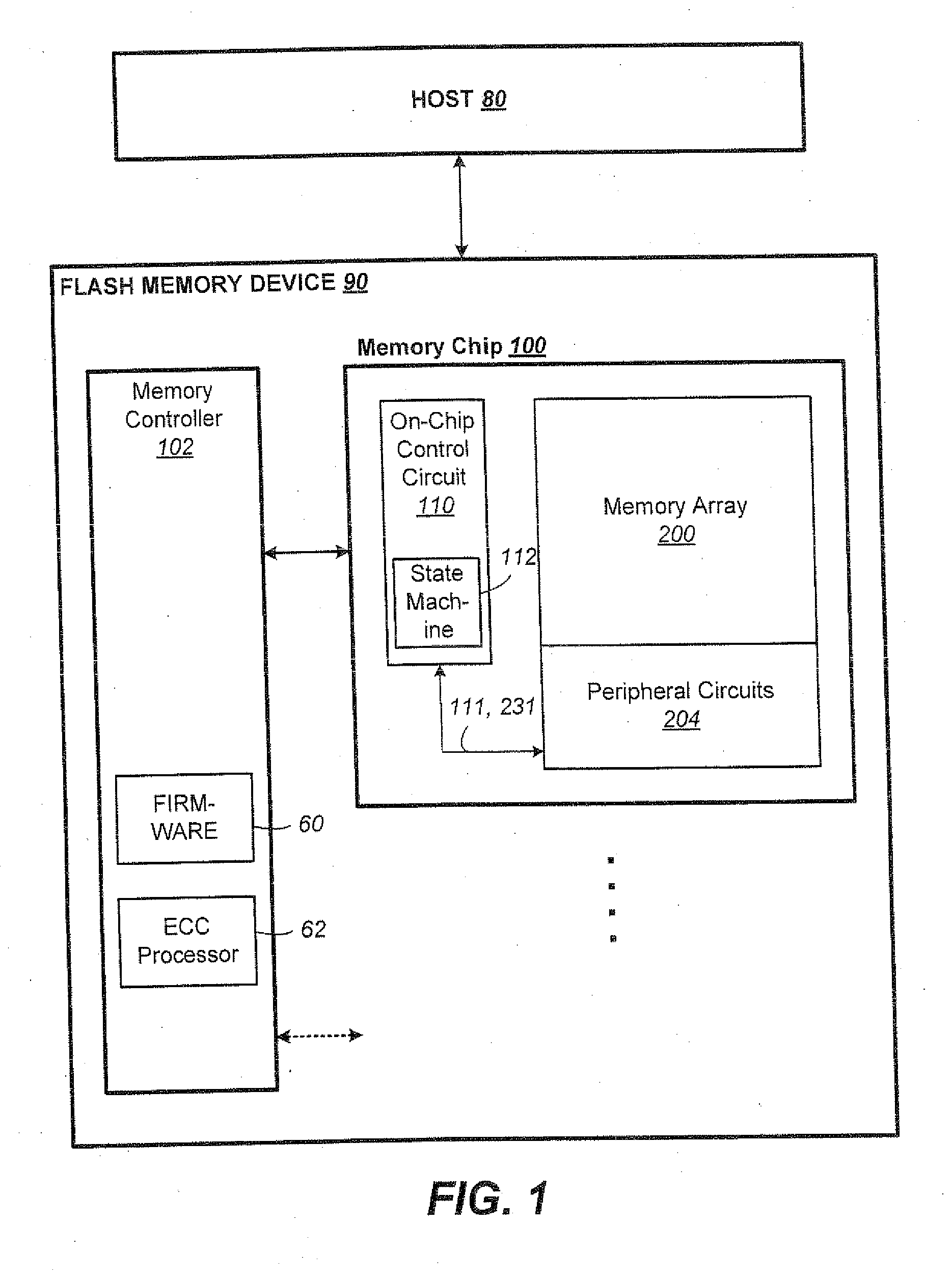
[0050]FIG. 1 illustrates a host in communication with a memory device in which the features of the present invention are embodied. The host 80 typically sends data to be stored at the memory device 90 or retrieves data by reading the memory device 90. The memory device 90 includes one or more memory chip 100 managed by a memory controller 102. The memory chip 100 includes a memory array 200 of memory cells with each cell capable of being configured as a multi-level cell (“MLC”) for storing multiple bits of data, as well as capable of being configured as a single-level cell (“SLC”) for storing 1 bit of data. The memory chip also includes peripheral circuits 204 such as row and column decoders, sense modules, data latches and I / O circuits. An on-chip control circuitry 110 controls low-level memory operations of each chip. The control circuitry 110 is an on-chip controller that cooperates with the peripheral circuits to perform memory operations on the memory array 200. Th...


PUM


Abstract

A non-volatile memory organized into flash erasable blocks sorts units of data according to a temperature assigned to each unit of data, where a higher temperature indicates a higher probability that the unit of data will suffer subsequent rewrites due to garbage collection operations. The units of data either come from a host write or from a relocation operation. Among the units more likely to suffer subsequent rewrites, a smaller subset of data super-hot is determined. These super-hot data are then maintained in a dedicated portion of the memory, such as a resident binary zone in a memory system with both binary and MLC portions.

Description

CROSS-REFERENCED APPLICATIONS[0001]This application is a Continuation in part of U.S. patent application Ser. No. 13 / 468,737, filed May 10, 2012, which in turn claims priority from U.S. Provisional Application No. 61 / 487,244 filed May 17, 2011, which applications are incorporated in their entirety by this reference.FIELD OF THE INVENTION[0002]This application relates to the operation of re-programmable non-volatile memory systems such as semiconductor flash memory, and, more specifically, to efficient storing of data in block structures while minimizing rewrites.BACKGROUND OF THE INVENTION[0003]Solid-state memory capable of nonvolatile storage of charge, particularly in the form of EEPROM and flash EEPROM packaged as a small form factor card, has become the storage of choice in a variety of mobile and handheld devices, notably information appliances and consumer electronics products. Unlike RAM (random access memory) that is also solid-state memory, flash memory is non-volatile, and...

Claims


Application Information

Patent Timeline
Patent Type & Authority Applications(United States)
IPC IPC(8): G06F12/02
CPCG06F12/0246G06F2212/7202G06F2212/7211G06F3/068G06F3/064G06F3/0679G06F3/0611
Inventor GOROBETS, SERGEY ANATOLIEVICHPARKER, LIAM MICHAELHUTCHISON, NEIL DAVIDYOUNG, ROBERT GEORGEBENNETT, ALAN DAVID
Owner SANDISK TECH LLC
Learn More