
Quantum processor based systems and methods that minimize an objective function

a technology of objective function and quantum processor, applied in the field of use of quantum processors, can solve the problems of difficult manufacturing on a commercial scale, prohibitive pre-processing, computationally exhaustive (and in some cases prohibitive), etc., and achieve the effect of improving accuracy, reducing cost and simplifying operation

Active Publication Date: 2014-07-03
D WAVE SYSTEMS INC
View PDF2 Cites 100 Cited by
  • Summary
  • Abstract
  • Description
  • Claims
  • Application Information

AI Technical Summary

Benefits of technology

The present patent is about using quantum processors to solve problems by operating them as a sample generator, which provides samples from a probability distribution over the states of the quantum processor. This approach can be useful for certain applications where the quantum processor is limited in its capabilities or there are problems that cannot be directly mapped to the quantum processor. The use of both quantum and digital processors in a hybrid system can produce more accurate and faster solutions. The techniques described herein can address problems with more variables and interactions between them. The approach simplifies the operation of quantum processors and reduces their dependence on the architecture. Users can interact with the quantum processor as a black box solver via a digital computer system.

Problems solved by technology

For example, such may allow the solution of problems which could not otherwise be solved, or problems which would require significantly larger processors (e.g., quantum processors with a much larger number of qubits and couplers) which are technically difficult to manufacture on a commercial scale and / or to maintain, or problems which may require computationally exhaustive (and in some cases, prohibitive) pre-processing in order to be directly mapped to a quantum processor.

Method used


Image

  • Quantum processor based systems and methods that minimize an objective function
  • Quantum processor based systems and methods that minimize an objective function
  • Quantum processor based systems and methods that minimize an objective function

Examples


Embodiment Construction

[0046]In the following description, some specific details are included to provide a thorough understanding of various disclosed embodiments. One skilled in the relevant art, however, will recognize that embodiments may be practiced without one or more of these specific details, or with other methods, components, materials, etc. In other instances, well-known structures associated with quantum processors, such as quantum devices, coupling devices, and control systems including microprocessors, drive circuitry and nontransitory computer- or processor-readable media such as nonvolatile memory for instance read only memory (ROM), electronically erasable programmable ROM (EEPROM) or FLASH memory, etc., or volatile memory for instance static or dynamic random access memory (ROM) have not been shown or described in detail to avoid unnecessarily obscuring descriptions of the embodiments of the present systems and methods. Throughout this specification and the appended claims, the words “ele...


PUM


Abstract

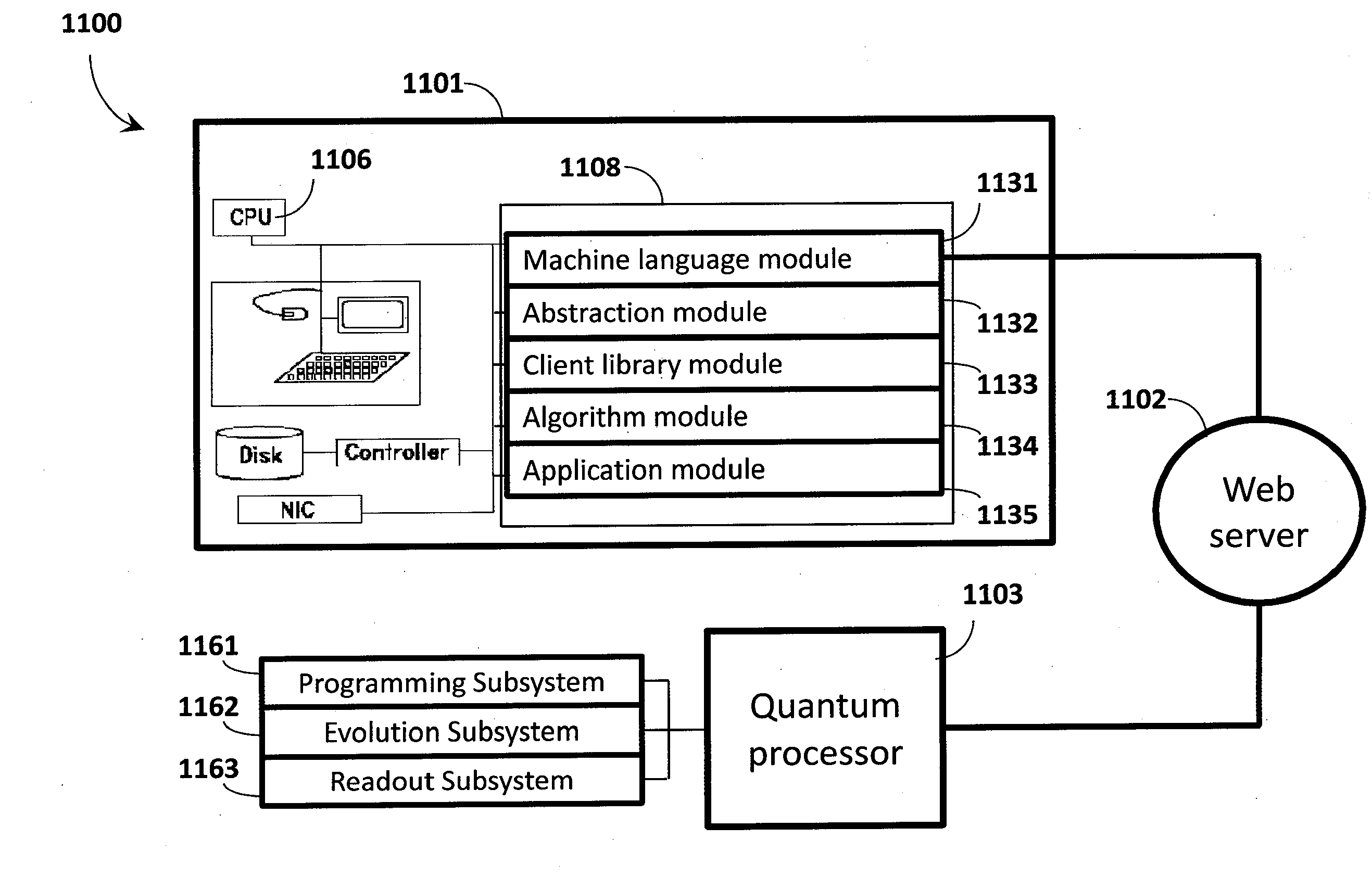
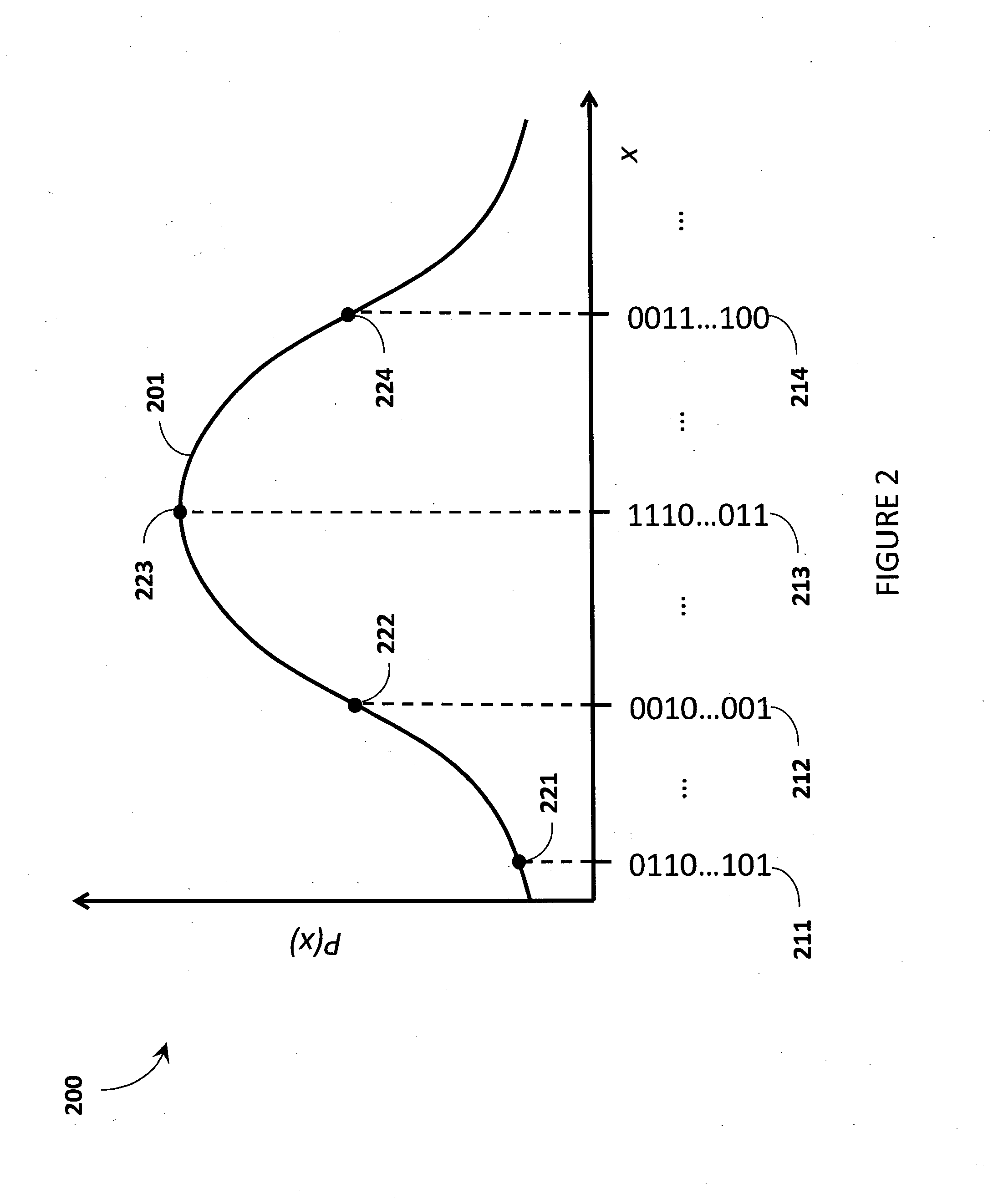
Quantum processor based techniques minimize an objective function for example by operating the quantum processor as a sample generator providing low-energy samples from a probability distribution with high probability. The probability distribution is shaped to assign relative probabilities to samples based on their corresponding objective function values until the samples converge on a minimum for the objective function. Problems having a number of variables and / or a connectivity between variables that does not match that of the quantum processor may be solved. Interaction with the quantum processor may be via a digital computer. The digital computer stores a hierarchical stack of software modules to facilitate interacting with the quantum processor via various levels of programming environment, from a machine language level up to an end-use applications level.

Description

CROSS REFERENCE TO RELATED APPLICATIONS[0001]This application claims benefit under 35 U.S.C. 119(e) of U.S. Provisional Patent Application Ser. No. 61 / 505,044, filed Jul. 6, 2011; U.S. Provisional Patent Application Ser. No. 61 / 515,742, filed Aug. 5, 2011; U.S. Provisional Patent Application Ser. No. 61 / 540,208, filed Sep. 28, 2011; U.S. Provisional Patent Application Ser. No. 61 / 550,275, filed Oct. 21, 2011; U.S. Provisional Patent Application Ser. No. 61 / 557,783, filed Nov. 9, 2011; U.S. Provisional Patent Application Ser. No. 61 / 569,023, filed Dec. 9, 2011; U.S. Provisional Patent Application Ser. No. 61 / 636,309, filed Apr. 20, 2012; and U.S. Provisional Patent Application Ser. No. 61 / 666,545, filed Jun. 29, 2012, each of which is incorporated herein by reference in its entirety.BACKGROUNDField[0002]The present systems and methods generally relate to use of quantum processors, and particularly relate to the use of quantum processors to minimize an objective function.Adiabatic Qua...

Claims


Application Information

Patent Timeline
IPC IPC(8): G06N5/02G06N99/00
CPCG06N99/002G06N5/02B82Y10/00G06N10/00G06N3/12G06N3/00G06N7/01
Inventor MACREADY, WILLIAM G.RANJBAR, MANIHAMZE, FIRASROSE, GEORDIEGILDERT, SUZANNE
Owner D WAVE SYSTEMS INC
Learn More