Enhanced evaporative cooling system

a technology of evaporative cooling and enhanced cooling, which is applied in chemical protection, nuclear engineering, nuclear elements, etc., can solve the problems of reducing cooling, waste of evaporative cooling potential of sweat, and less surface area, and achieves enhanced evaporative cooling of the body and better use of water. the effect of the expression

Inactive Publication Date: 2008-12-18
HORN STEPHEN T +1
View PDF26 Cites 2 Cited by
  • Summary
  • Abstract
  • Description
  • Claims
  • Application Information

AI Technical Summary

Benefits of technology

[0010]When there is inadequate sweat as in very arid environments a minute amount of water from a water source can be inserted into the vest by a pump such as a squeeze bulb. A squeeze bulb pump with a canteen used for a water source was tested at Kansas State University, Institute for Environmental Research for use in injecting water under the vest to enhance the evaporative cooling of the vest and the blocking of environmental heat.
[0011]Another important aspect of the present invention is the plenum which conducts the air which removes the heat from around the body. The heat being transferred to a gas needs to be exhausted from the space between the body or torso and the vest. Once this air is saturated no further evaporative cooling is possible. However with very large volumes of even humid air evaporative cooling is effective. The plenum is designed to absolutely minimize obstructions to the flow of air. Rather than duct air through tubes as is normally done; the present invention eliminates tubing for the conduction of air and creates the plenum from the use of the torso as one surface and the vest as the other surface. The vest forming one large pipe in one sense and the torso being inserted into this pipe. This unobstructed air flow allows the transmission of large quantities of air with little back pressure and very importantly at very little energy costs from batteries. The inventor has a patent filed on the supporting structure for such air flow in a vest where the torso or body has a supporting structure to support the vest away from the body. This has also been shown to be effective at tests at Kansas State University where the air flow is large enough for tee shirts worn by the soldiers to be dry except where the supporting structure touches the torso and blocks evaporation from the tee shirt. The patent application Ser. No. is 11 / 361,866 filed by Stephen T. Horn on Feb. 24, 2006.

Problems solved by technology

First, beaded sweat has far less surface area than skin that is just damp.
This reduced surface area consequently reduces evaporation and reduces cooling.
Importantly the evaporative cooling potential of the water in the sweat is wasted as it is allowed to drip to the ground or in the case of the torso, to drip or run down the back of the person.
When water from sweat can be transferred as a liquid from the body as by contact with another surface then effective cooling through the phase shift of that water is wasted.

Method used


Image

  • Enhanced evaporative cooling system
  • Enhanced evaporative cooling system
  • Enhanced evaporative cooling system

Examples


Embodiment Construction

)

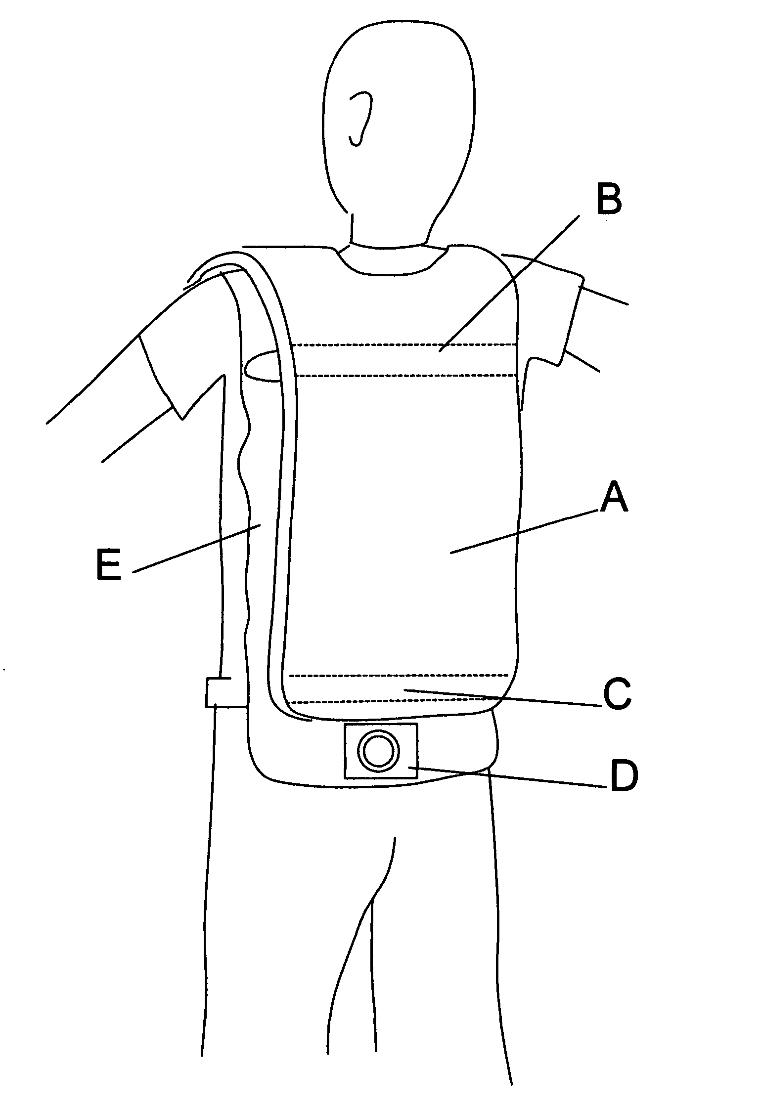
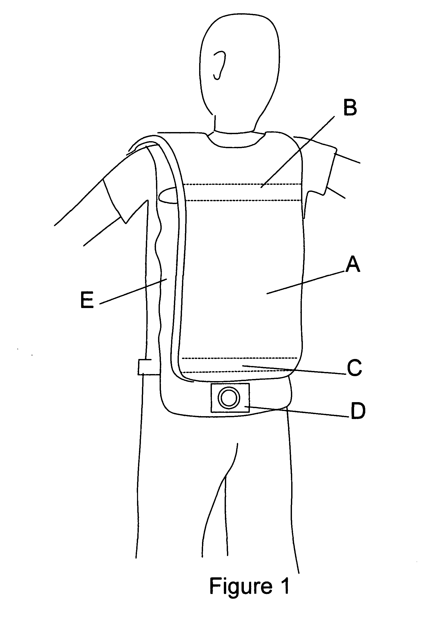
[0017]FIG. 1A sheet 1 is a protective vest such as the Interceptor vest. The protective vest is supported from the body by structures B and C in FIG. 1 sheet 1. FIG. 1E sheet 1 is an absorbent material such as cotton cloth however any material that will transfer moisture will work. Even plastic will blot water from a surface. FIG. 1E sheet 1 is separate from the Interceptor vest in this embodiment but it could be an integral part of the protective vest. D in FIG. 1 sheet 1 is a blower that blows air under the absorbent layer FIG. 1E sheet 1. The air from the blower will remove moisture through evaporation and cool the wearer. Humid conditions require more air but still cools the individual. The volume of the air necessary is proportional to the relative humidity until the air being pumped in is one hundred percent saturated.

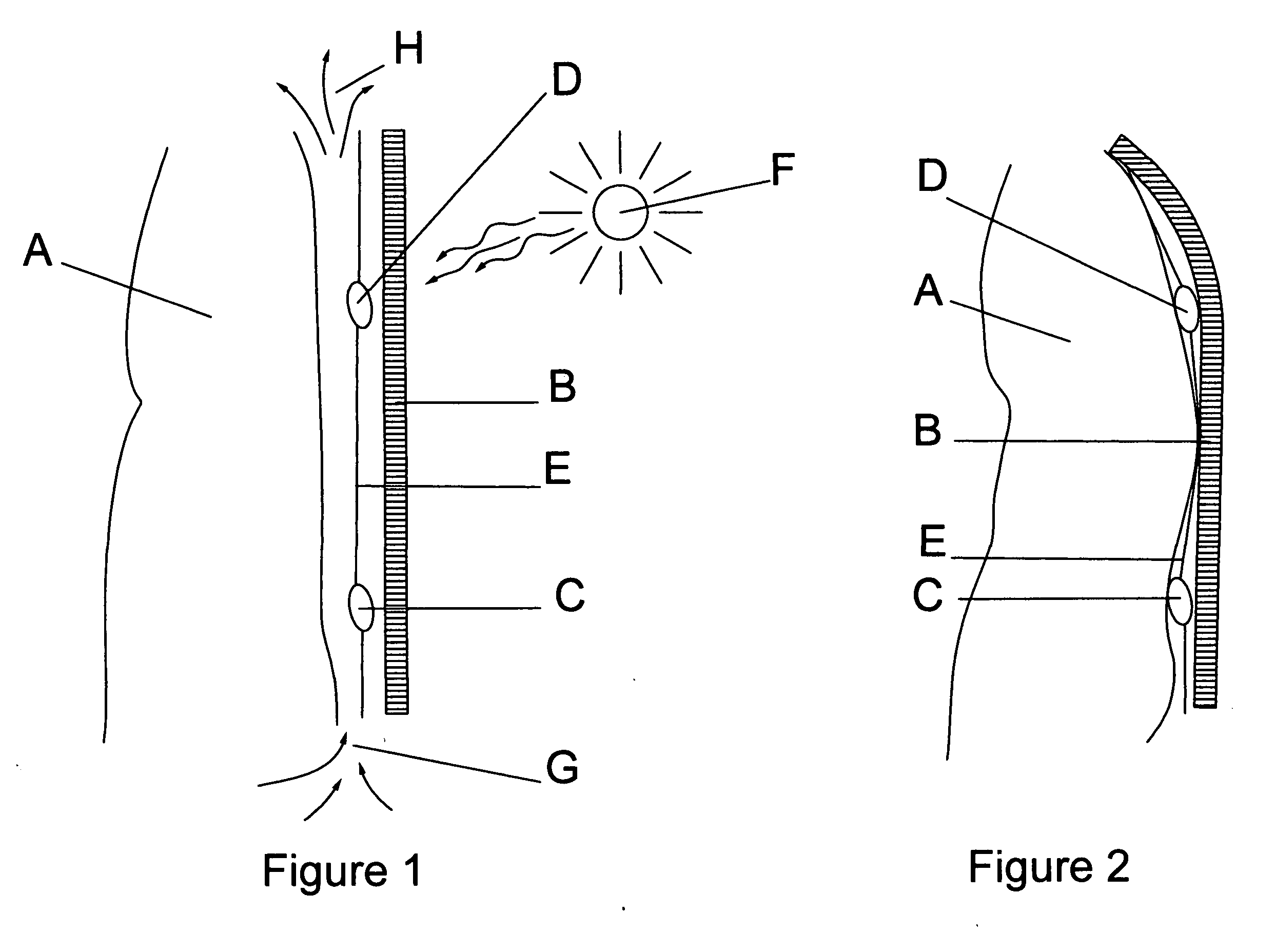
[0018]FIG. 1 sheet 2 shows a cross section of the sectional side view of the torso with absorbent material and protective vest and shows the absorption of envir...


PUM


Abstract

A blower operated cooling vest that uses the normal movement of the body to blot excess moisture from the body and evaporate it away from the body and thus shield it from the heat.

Description

CROSS-REFERENCE TO RELATED APPLICATIONS [0001]NoneFEDERALLY SPONSORED RESEARCH [0002]NoneSEQUENCE LISTING [0003]None1. FIELD OF THE INVENTION[0004]The present invention provides a means to use air by a fan or blower device to increase the evaporation of available moisture from an individual and thus cool them while they are wearing heavy protective equipment such as a military tactical vest. The present device through a blotting action removes moisture from individual and through wicking distributes this moisture throughout the fabric of the vest where it is then evaporated by the air flow and hence removes heat from being transferred from the outer protective vest to the individual.2. DESCRIPTION OF THE PRIOR ART[0005]U.S. Pat. No. 5,217,408 by Kaine issued on Jun. 8 1993 discusses a cooling vest that has a fan and a cowling to contain the pumped air. The present invention does not teach a blotting action to actively remove excess heat from the plenum surrounding the body. The pres...

Claims


Application Information

Patent Timeline
Patent Type & Authority Applications(United States)
IPC IPC(8): A41D13/005
CPCA41D13/0053
Inventor HORN, STEPHEN T.
Owner HORN STEPHEN T
Why Eureka
Try Eureka