Vacuum insulated switchgear

a switchgear and vacuum insulation technology, applied in the direction of switchgear arrangement, high-tension/heavy-dress switch, air-break switch, etc., can solve the problems of reducing the installation space, suppressing the investment for the installation, and no device and facility responding

Inactive Publication Date: 2008-12-18
HITACHI LTD
View PDF8 Cites 34 Cited by
  • Summary
  • Abstract
  • Description
  • Claims
  • Application Information

AI Technical Summary

Benefits of technology

[0008]In view of the above problem, the present invention is achieved. An object of the present inven...

Problems solved by technology

In this case, it becomes a problem how to reduce an installation space for the above devices and controlling, monitoring, instrumentation, ...

Method used


Image

  • Vacuum insulated switchgear
  • Vacuum insulated switchgear
  • Vacuum insulated switchgear

Examples


Embodiment Construction

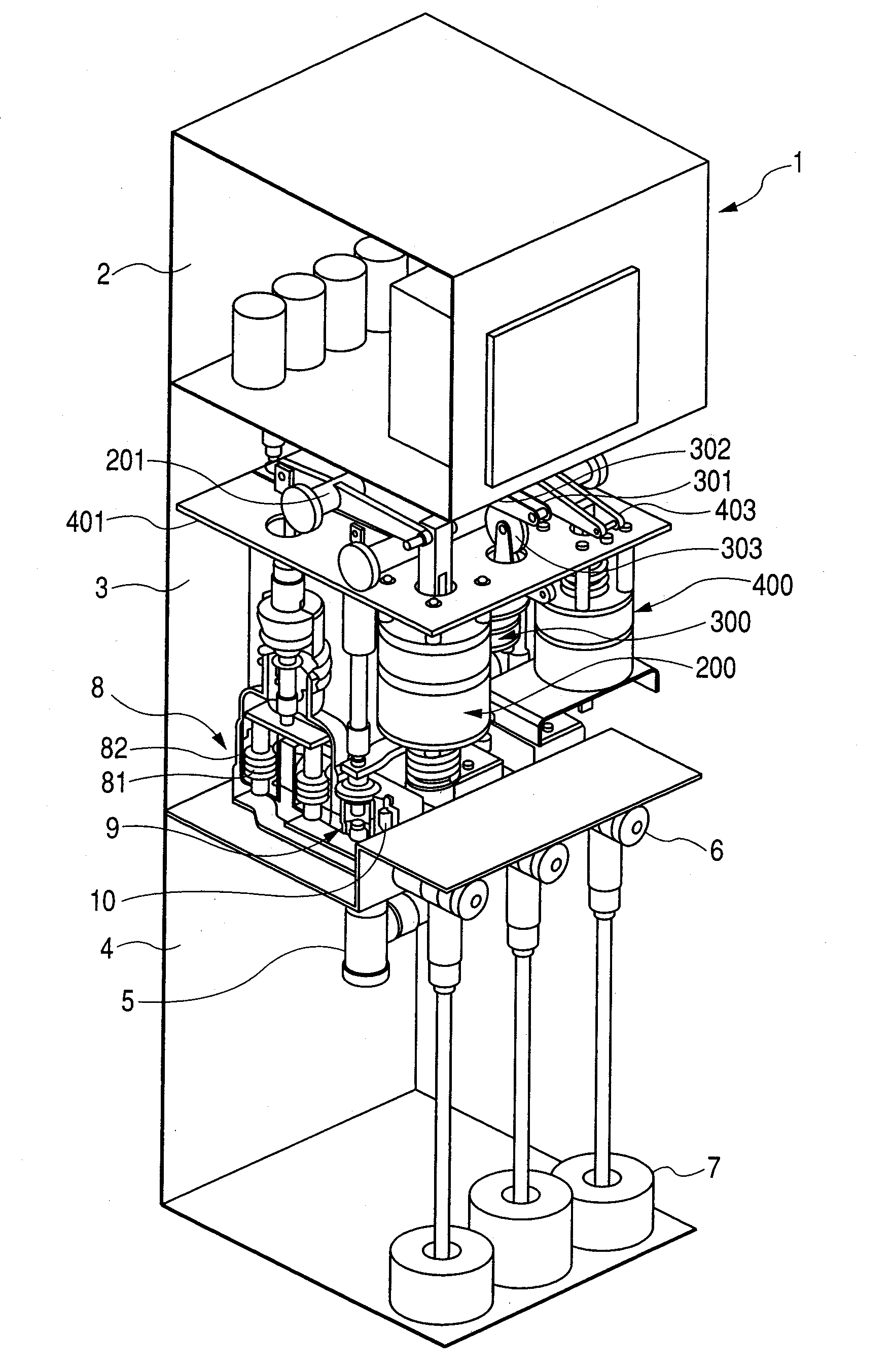
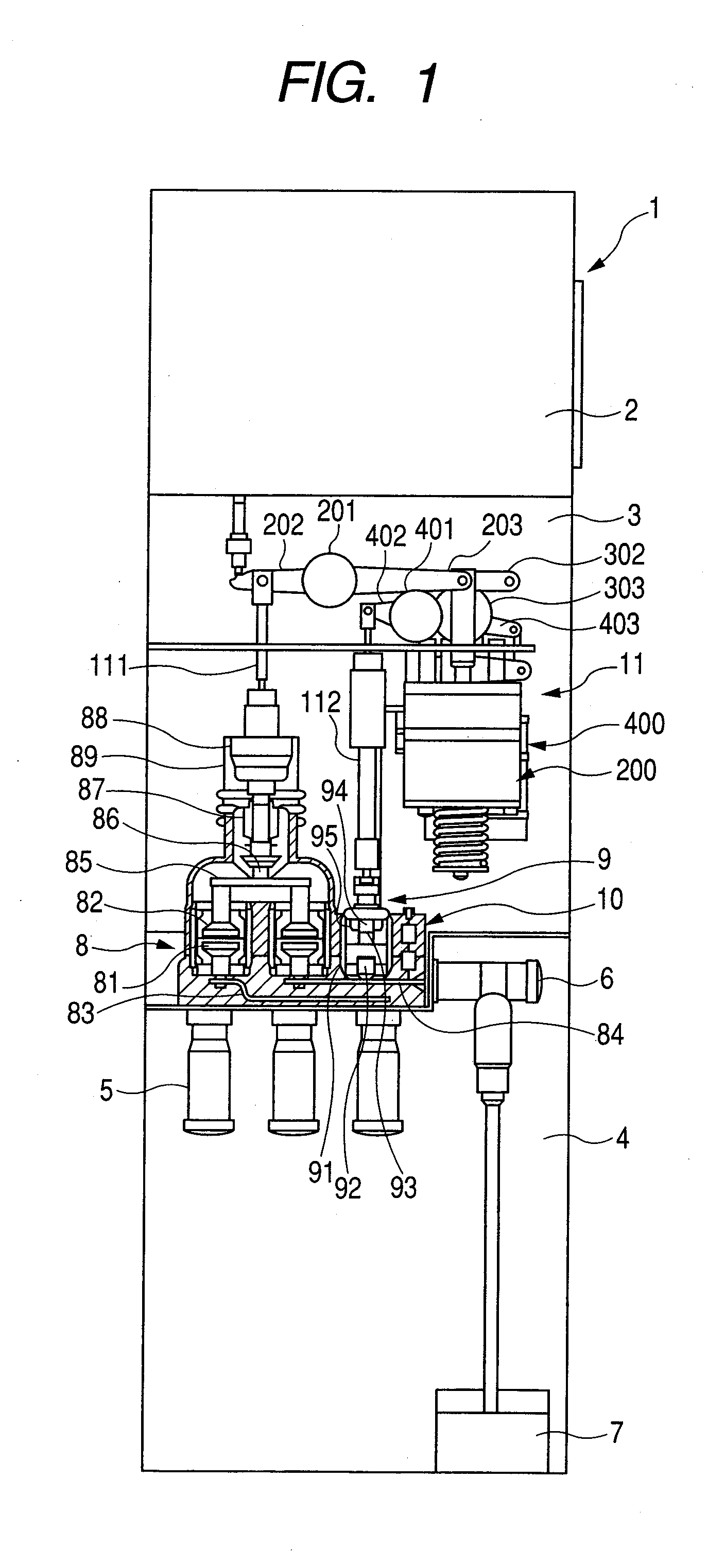
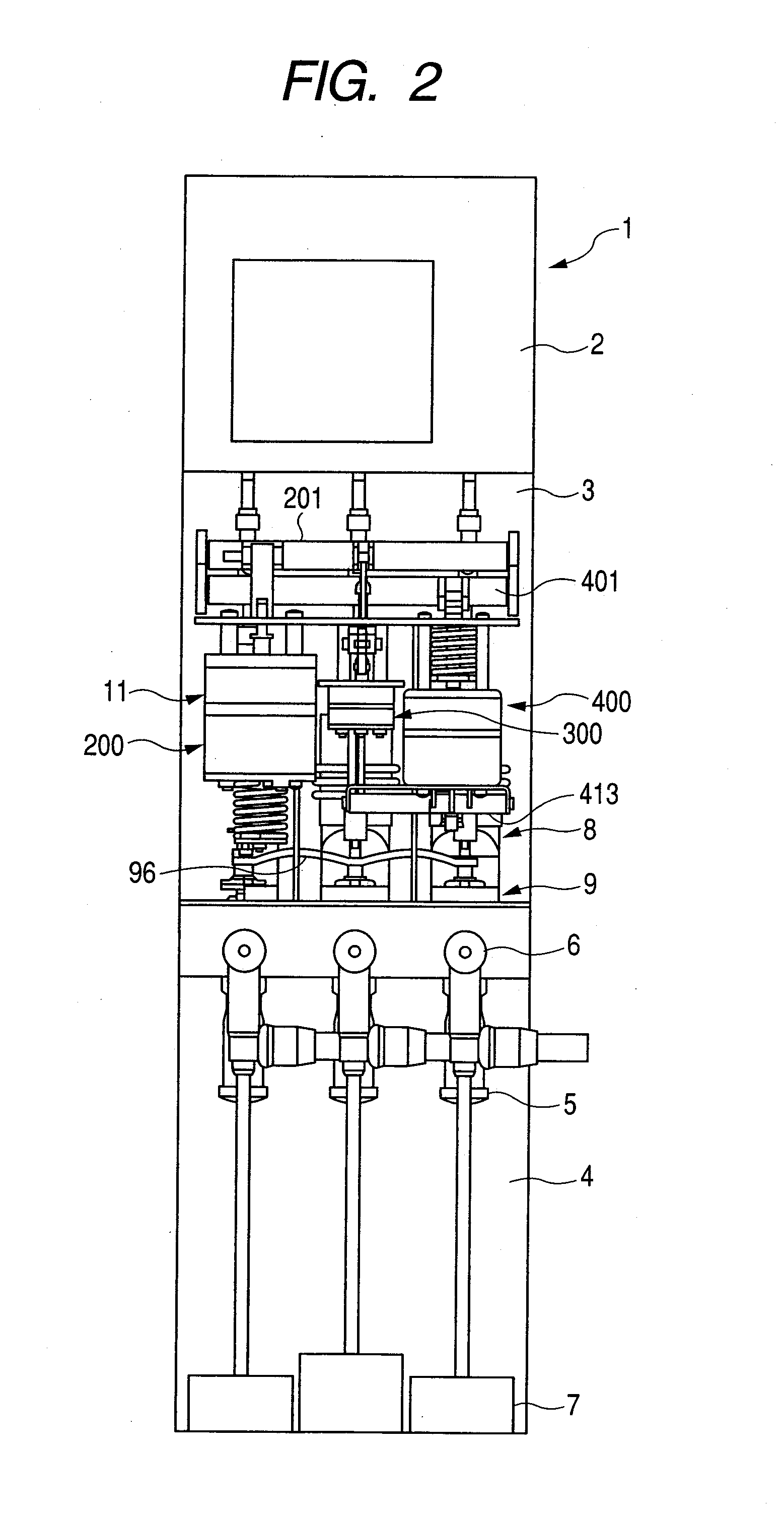
[0022]To achieve the above object, a first aspect of the invention is a vacuum insulated switchgear characterized in comprising a vacuum double-break three-position type switch having both of breaking and disconnecting functions.

[0023]A second aspect of the invention is the vacuum insulated switchgear characterized in comprising the vacuum double-break three-position type switch having the breaking and disconnecting function, wherein the switch has an isolated-phase structure.

[0024]A third aspect of the invention is the vacuum insulated switchgear characterized in comprising: the vacuum double-break three-position type switch having the breaking and disconnecting functions; a line connected to one of fixed contacts of the switch; a bus connected to the other of the fixed contacts of the switch; and a vacuum earthing switch connected to the line.

[0025]A forth aspect of the invention is the vacuum insulated switchgear characterized in comprising: the vacuum double-break three-position...


PUM


Abstract

A vacuum insulated switchgear comprising a vacuum container accommodating at least a pair of movable contacts and a pair of fixed contacts, wherein the movable contacts are capable of taking three positions, the switchgear being a double-break three-position type switch having breaking and disconnecting functions.

Description

TECHNICAL FIELD[0001]The present invention relates to a vacuum insulated switchgear which is reduced in size and weight to have high capability and reliability.BACKGROUND ART[0002]In power receiving facilities, a closed type distributor (called a switchgear) is provided in which a vacuum circuit breaker for breaking load current or accident current, a disconnecting switch and earth switch for ensuring safety of an operator in maintaining the load, a detector for system voltage and current, a protection relay, and the like are contained.[0003]There are various insulation methods for switchgears. Solid insulation, compressed air insulation, full vacuum insulation, and the like have appeared in recent years in view of environment, in addition to a conventional air insulation panel and cubicle GIS using SF6 gas. Downsizing of components of the breaker, disconnecting switch, and earth switch has been accelerating in various insulation methods. A switchgear (intensive type switchgear) in ...

Claims


Application Information

Patent Timeline
IPC IPC(8): H01H33/66
CPCH01H31/003H01H33/6661H01H33/668H01H2033/6668H02B13/0354
Inventor TSUCHIYA, KENJIKOBAYASHI, MASATOMORITA, AYUMU
Owner HITACHI LTD
Why Eureka
Try Eureka