
Package structure of light emitting diode for backlight

a technology of light-emitting diodes and package structures, which is applied in the direction of basic electric elements, electrical equipment, and semiconductor devices, can solve the problems of unharmonious light dots, different working life of leds, and disproportionate spectrum of light, and achieve the effect of increasing the color rendering index of the package structur

Inactive Publication Date: 2008-12-18
ADVANCED OPTOELECTRONICS TECH
View PDF1 Cites 38 Cited by
  • Summary
  • Abstract
  • Description
  • Claims
  • Application Information

AI Technical Summary

Benefits of technology

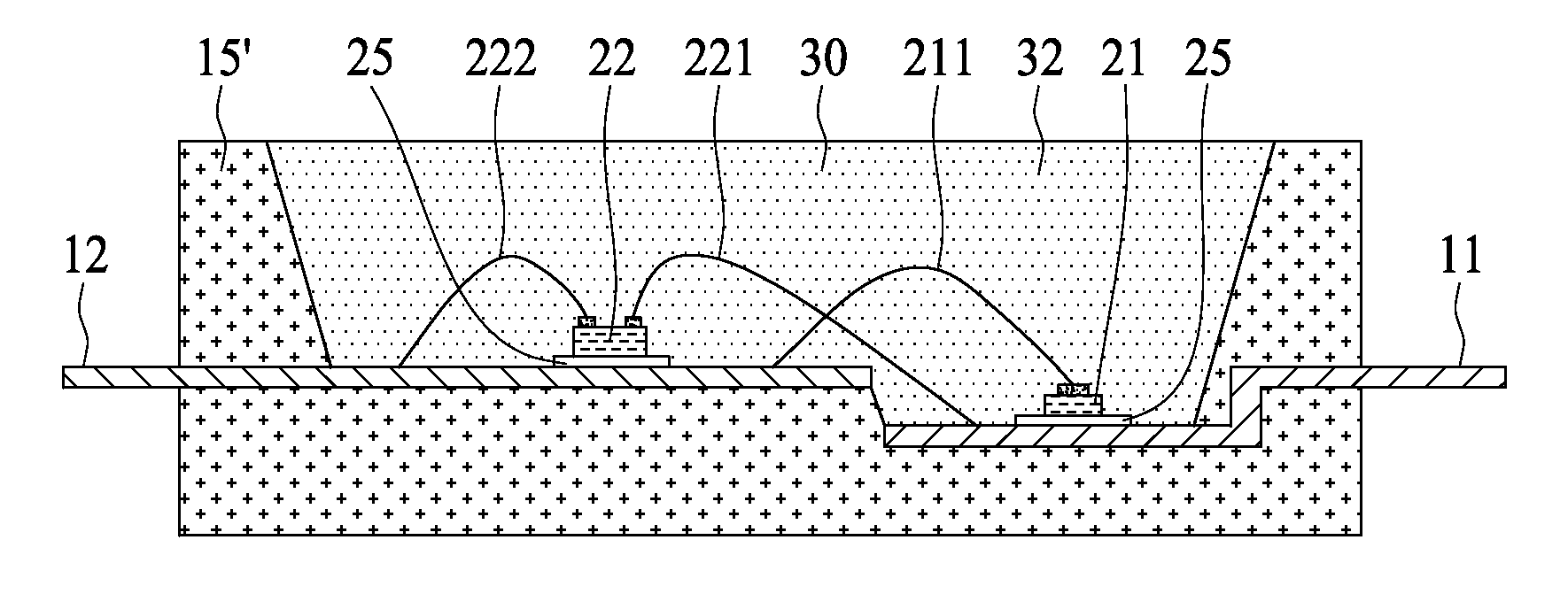
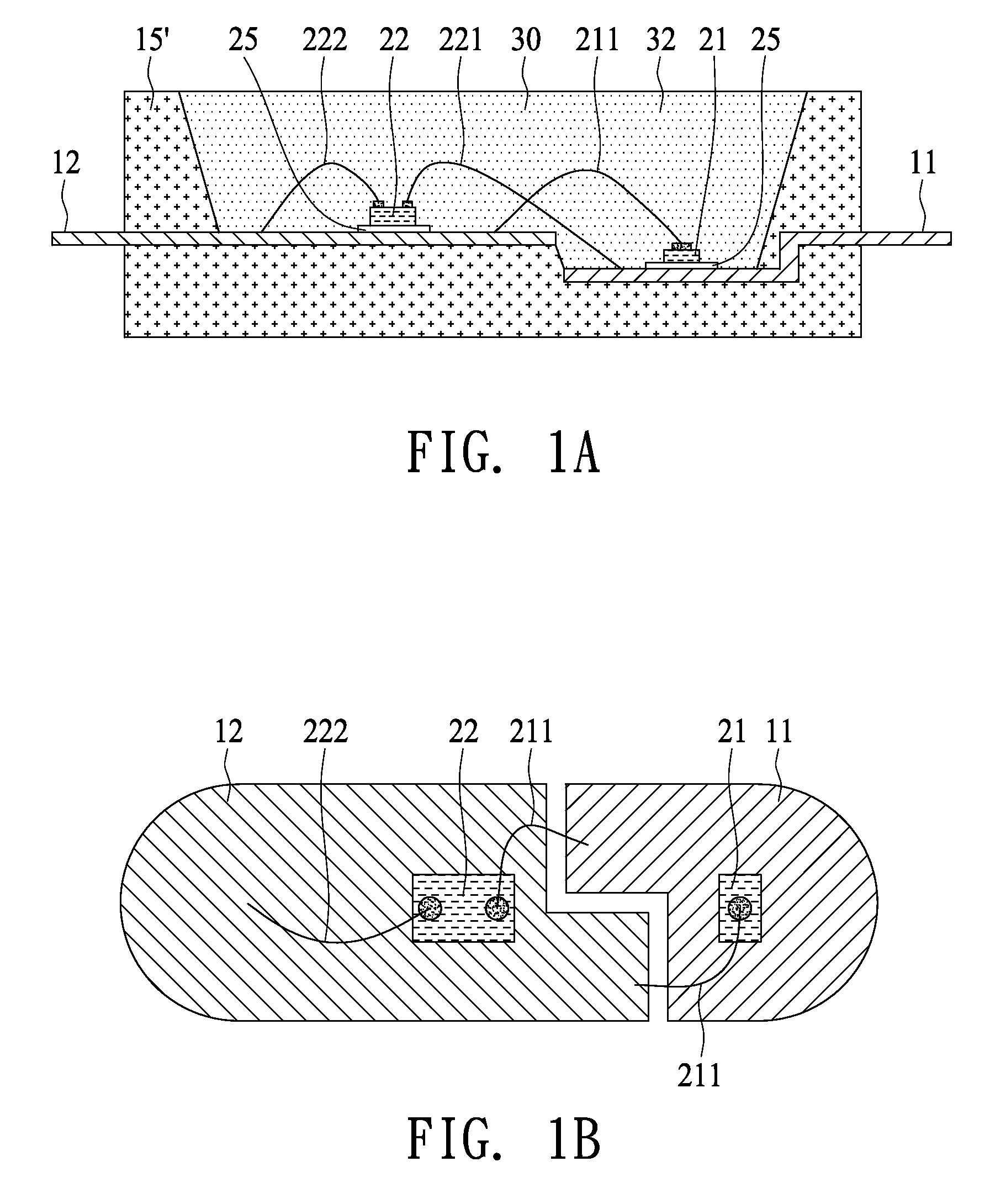
[0007]Furthermore, an aspect of the present invention is to partition a package structure into two compartments for a long-wavelength LED die and a short-wavelength LED die respectively so that the light emitted from the long-wavelength LED die cannot be blocked by fluorescent powders and is more efficiently used in the light output of the package structure.
[0008]Another aspect of the present invention is to improve the light emitted from a long-wavelength LED die so that the color rendering index of the package structure is increased. An LCD (liquid crystal display) panel using such an LED device can show a larger quantity of colors.

Problems solved by technology

However, such a white light, a mixture of red, blue and green lights, is disproportionate in its spectrum.
In addition, the working life of one LED is different from that of another.
Accordingly, when one color light LED fails, the change in the mixed light is obvious so that a viewer easily sees an unharmonious light dot.
However, such a light mixture for the application of a backlight is insufficient in the intensity of red light so that its color rendering index is lower.
However, the adjusting method is too complicated.

Method used


Image

  • Package structure of light emitting diode for backlight
  • Package structure of light emitting diode for backlight
  • Package structure of light emitting diode for backlight

Examples


Embodiment Construction

[0017]The following will demonstrate the present invention using the accompanying drawings to clearly present the characteristics of the technology.

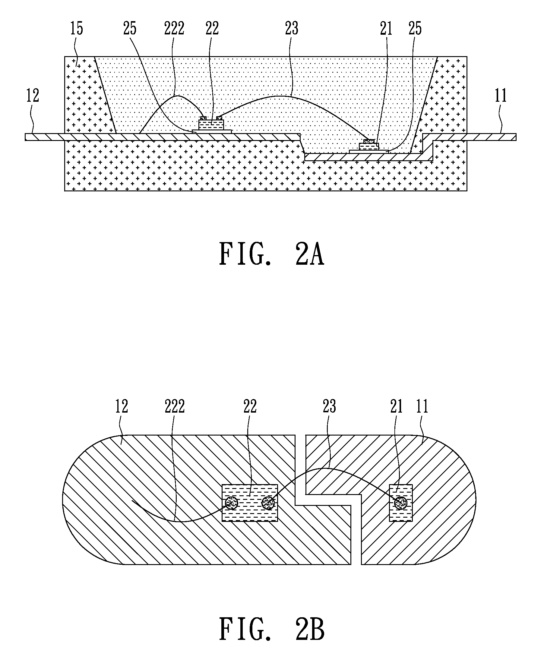
[0018]The present invention provides a package structure comprising two LED dies respectively emitting lights with different wavelengths. Such a package structure is implemented by using a substrate with different levels or a partition plate disposed between the long-wavelength and short-wavelength LED dies so that the long-wavelength LED die cannot absorb the light emitted from the short-wavelength LED die. The lights emitted from the short-wavelength LED die are mixed with the light emitted from excited fluorescent powders in the package structure. In this regard, short wavelength means that the peak wavelength of the light of an LED die ranges from 360 nm to 490 nm. In general, a blue LED die is used as the short-wavelength LED die, and, moreover, a purple LED die or a UV LED die can be used as the short-wavelength LED die. Long wavel...


PUM


Abstract

A package structure of a light emitting diode for a backlight comprises a long-wavelength LED die and a short-wavelength LED die. The lights emitted from the two LED dies are mixed with the light emitted from excited fluorescent powders for serving as the backlight of a liquid crystal display. A partition plate is disposed between the two LED dies for separating them from each other. The effective light output of the package structure is increased because each of the two LED dies cannot absorb the light from the other.

Description

BACKGROUND OF THE INVENTION[0001](A) Field of the Invention[0002]The present invention relates to a package structure of a light emitting diode (LED) for a backlight, and more particularly, to a long-wavelength LED for increasing the color rendering index of a backlight.[0003](B) Description of the Related Art[0004]An LED is a semiconductor device, and can serve as a light source with a small volume effectively emitting high-intensity light. Moreover, the light of the LED has a superior mono-color peak in its spectrum. If a white light is generated by LEDs, several color lights emitting from the LEDs need to be mixed. A simple way to get a white light is to simultaneously use red, blue and green LEDs. However, such a white light, a mixture of red, blue and green lights, is disproportionate in its spectrum. A proportionate white light is obtained by mixing various color lights in a complicated optical manner. Furthermore, the brightness of an LED varies with the temperature of the LE...

Claims


Application Information

Patent Timeline
Patent Type & Authority Applications(United States)
IPC IPC(8): H01L33/00
CPCH01L25/0753H01L33/483H01L33/504H01L2924/09701H01L2224/48091H01L2224/48137H01L2224/48247H01L2224/48465H01L2924/00014H01L2924/00
Inventor TSANG, JIAN SHIHNTSENG, WEN LIANGTSENG, YAO TECHAN, SHIH HSIUNG
Owner ADVANCED OPTOELECTRONICS TECH
Learn More