Sheet processing apparatus and sheet processing method
a technology of processing apparatus and sheet, which is applied in the direction of electrographic process, instruments, transportation and packaging, etc., can solve the problems of difficulty in stopping a sheet, deviating the position of the punch hole, and requiring high-speed processing measures, so as to achieve accurate skew correction, reduce the time of skew correction, and improve the effect of speed
- Summary
- Abstract
- Description
- Claims
- Application Information
AI Technical Summary
Benefits of technology
Problems solved by technology
Method used
Image
Examples
second embodiment
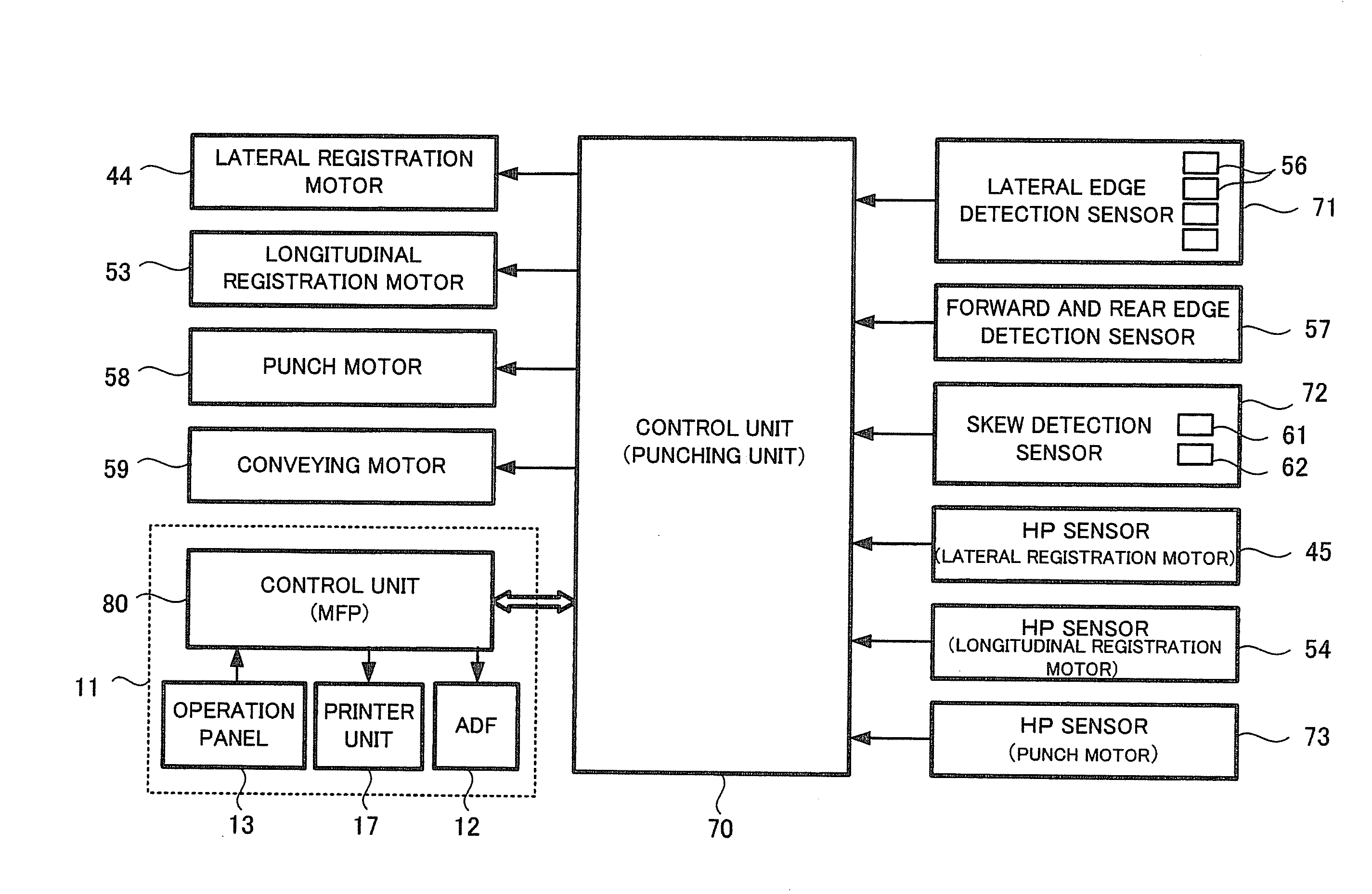
[0140]Thus, the invention is characterized in that the time required for the reciprocating movement of the hole punching section 35 is reduced. The movement control of the hole punching section 35 is carried out by the control unit 70.
[0141]FIG. 11A to FIG. 11D are views for explaining the operations of the punching unit 31 according to the second embodiment of the invention. The operation of skew correction will not be described.
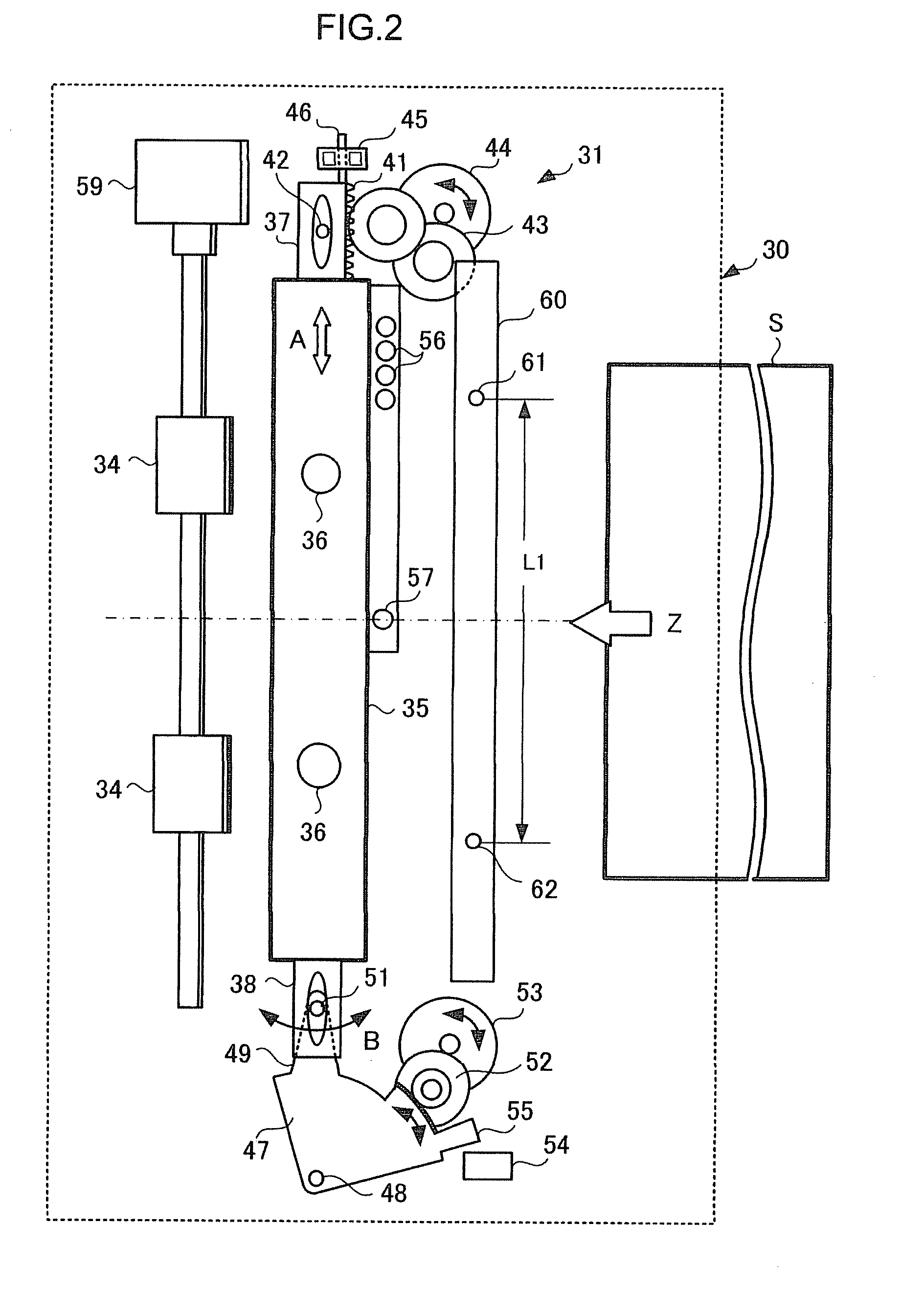
[0142]In the state shown in FIG. 11A, the hole punching section 35 is situated at a center position in the sheet conveying path or at a position where punching processing is carried out to the preceding sheet, and a sheet is conveyed thereto. In this state, the lateral registration motor 44 is driven next and the hole punching section 35 moves in the direction toward the retreat position (the direction of the arrow A1). At this time, the hole punching section 35 moves while the lateral edge of the sheet S is detected by the sensor group 56.
[0143]When the la...
third embodiment
[0175]Thus, in the invention, another measure is taken in the technique of skew correction. Specifically, the invention is characterized in that, in the case where the quantity of skew at the forward edge exceeds the skew correction range w2 (±6 pulses) at the rear edge, skew correction at the forward edge is carried out by the amount equivalent to the skew correction range w2 (±6 pulses) at the rear edge, and the insufficient correction is compensated for by skew correction at the rear edge.
[0176]For example, when the quantity of skew correction at the forward edge is equivalent to a prescribed number of pulses (for example, ±6 pulses) or less, the hole punching section 35 is turned in proportion to the quantity of skew at the forward edge. On the other hand, when the quantity of skew correction at the forward edge exceeds the prescribed number of pulses (for example, ±6 pulses) the way of controlling the turning varies.
[0177]The operation in the case where the quantity of skew at ...
fourth embodiment
[0197]Thus, in the invention, an improvement is made so that the forward and rear edges of the sheet S are detected by using the sensors 61 and 62 of the skew detection unit 60, and the forward edge and rear edge detection sensor 57 of FIG. 2 is omitted.
[0198]Hereinafter, a sheet processing apparatus according to the fourth embodiment of the invention will be described with reference to FIG. 19.
[0199]In FIG. 19, a punching mechanism 30 has a punching unit 31. The punching unit 31 has the function of performing punching processing to the sheet S and correcting skew of the sheet S. The punching unit 31 has a hole punching section 35 which punches punch holes in the sheet S conveyed therein from the image forming apparatus 10, and a skew detection unit 60 for detecting skew.
[0200]The configuration of the hole punching section 35 is the same as the configuration shown in FIG. 2 and therefore will not be described further in detail. To control movement of the hole punching section 35 in ...
PUM
| Property | Measurement | Unit |
|---|---|---|
| distance | aaaaa | aaaaa |
| distance | aaaaa | aaaaa |
| tilt angle | aaaaa | aaaaa |
Abstract
Description
Claims
Application Information
 - R&D
- Intellectual Property
- Life Sciences
- Materials
- Tech Scout
- Unparalleled Data Quality
- Higher Quality Content
- 60% Fewer Hallucinations
Browse by: Latest US Patents, China's latest patents, Technical Efficacy Thesaurus, Application Domain, Technology Topic, Popular Technical Reports.
© 2025 PatSnap. All rights reserved.Legal|Privacy policy|Modern Slavery Act Transparency Statement|Sitemap|About US| Contact US: help@patsnap.com


