Digital current share bus interface

a current share and bus technology, applied in the direction of electric variable regulation, process and machine control, instruments, etc., can solve the problems of increasing the total current capacity of a multi-module system, increasing the power dissipation of modules, and thus becoming hotter than other modules, and reducing the reliability of the overall power system

Active Publication Date: 2008-12-18
ANALOG DEVICES INC
View PDF6 Cites 41 Cited by
  • Summary
  • Abstract
  • Description
  • Claims
  • Application Information

AI Technical Summary

Benefits of technology

[0013]A power module, typically one of several having their outputs connected in parallel, is arranged to provide an output signal (preferably a digital signal) representative of its output current, and to adjust its output current in response to a signal received at a control input. The present interface includes a digital controller which comprises a data formatting module and a comparator module. The data formatting module receives the output signal representative of the power module's output current and generates a digital word which varies with the output current; the bits of the digital word are coupled to a current share bus. The data formatting module is preferably arranged such that a clock for the bus is modulated onto the data conveyed on the bus.
[0014]The comparator module receives digital words conveyed via the bus and generated by the data formatting module at respective inputs, and provides the control signal to the power module so as to adjust its output current to match the current value represented by the digital word on the bus.

Problems solved by technology

Furthermore, simply supplementing the design with additional power modules may increase the total current capacity of a multi-module system.
If one module delivers a greater amount of current, that module will dissipate more power and therefore become hotter than the other modules.
Higher operating temperature normally yields reduced reliability of the overall power system.
If the current supplied by the power system is evenly divided among the power modules, each module will deliver an equal amount of power, and no one module will be driven to an extreme that may cause power conversion inefficiencies, power module degradation or premature power module failure.

Method used


Image

  • Digital current share bus interface
  • Digital current share bus interface
  • Digital current share bus interface

Examples


Embodiment Construction

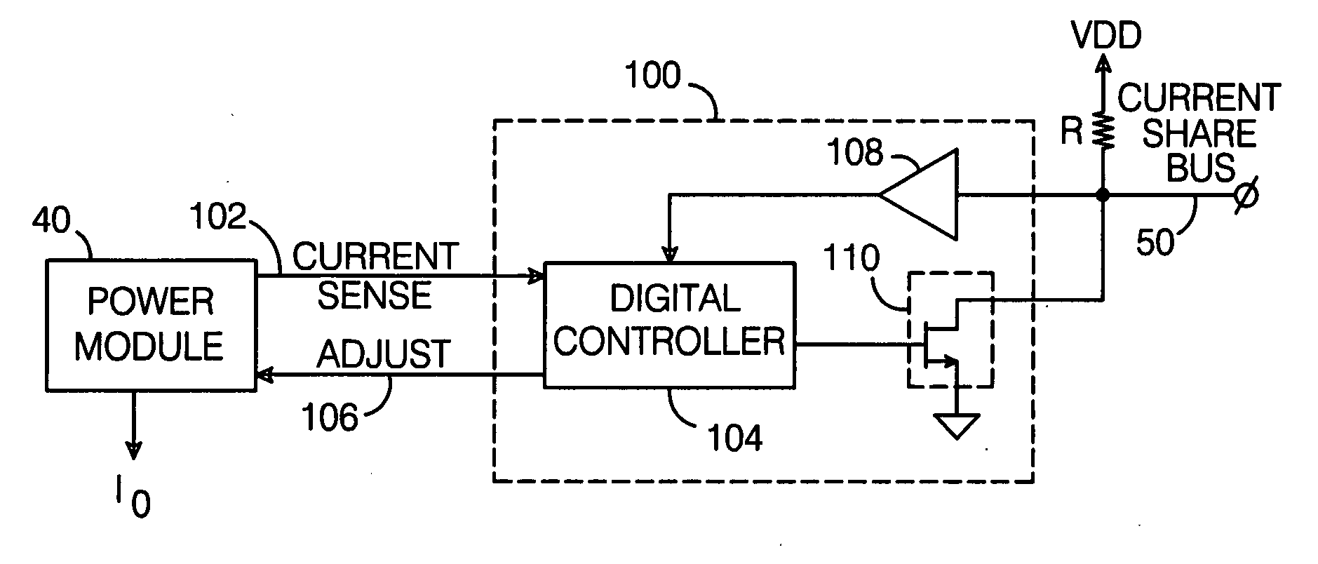
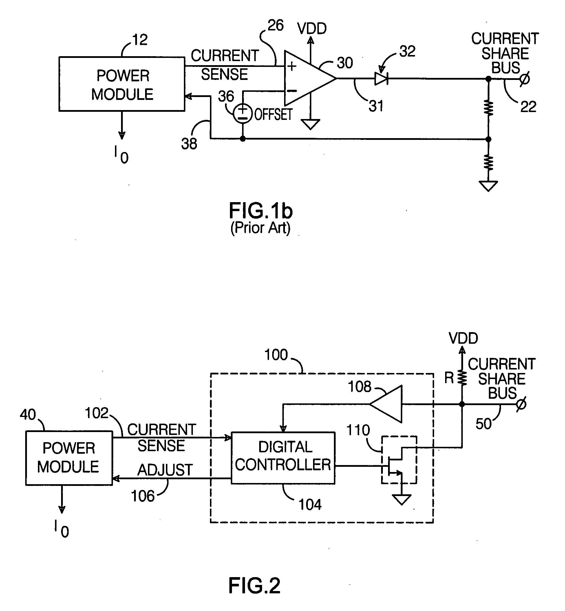
[0025]A diagram illustrating the principles of a digital current share bus interface 100 per the present invention is shown in FIG. 2. The interface operates between a power module 40 and a digital current share bus 50. In operation, interface 100 receives current sense information 102 which represents the output current (I0) of power module 40 and conveys it to share bus 50, receives output current information being conveyed via bus 50, and causes the output current of power module 40 to be adjusted as necessary to make it approximately equal to the output current value on the bus. In a typical application, there are multiple power modules like module 40 having their output currents connected in parallel, and multiple interfaces 100 coupling respective power modules to current share bus 50.

[0026]Note that for purposes of illustration, only the sharing of output current information via a share bus is described herein. However, data other than that related to output currents could al...


PUM


Abstract

A digital current share bus interface connects to a power module which provides a signal representative of its output current, and adjusts the module's output current in response to a control signal received from the interface. A data formatting module receives the output current signal and generates a digital word that varies with the current; the bits of the word are coupled to a current share bus. A comparator module receives digital words conveyed via the bus and generated by the data formatting module at respective inputs, and provides the control signal to the power module so as to adjust its output current to match the current value represented by the digital word on the bus. In a typical implementation, multiple power modules are coupled to the current share bus via respective interfaces, with the output currents of all the power modules connected in parallel.

Description

BACKGROUND OF THE INVENTION[0001]1. Field of the Invention[0002]This invention relates generally to the field of current share busses designed to enable a load current to be shared equally between multiple power modules, and more particularly to a digital implementation of an interface for such a bus.[0003]2. Description of the Related Art[0004]It is often advantageous to implement a power system using a plurality of individual DC-to-DC or AC-to-DC power modules or supplies connected in parallel. (“Power module” in this context refers to a voltage / current converter, not to the ultimate source of electric current such as a battery or generator). Unlike a single module power source, a multi-module power system can provide for failure recovery if one module ceases to operate. Furthermore, simply supplementing the design with additional power modules may increase the total current capacity of a multi-module system. Often such power systems are used in telecommunications equipment and ot...

Claims


Application Information

Patent Timeline
Patent Type & Authority Applications(United States)
IPC IPC(8): G05F1/565
CPCH02J1/102H02M3/157H02M3/285H02J1/001
Inventor LIU, CHAOBAKKER, ANTHONIUS
Owner ANALOG DEVICES INC
Why Eureka
Try Eureka