Low-loss tunable radio frequency filter

Active Publication Date: 2008-12-18
MURATA MFG CO LTD
View PDF13 Cites 29 Cited by
  • Summary
  • Abstract
  • Description
  • Claims
  • Application Information

AI Technical Summary

Benefits of technology

[0019]In accordance with a third aspect of the present inventions, a method of tuning a RF filter having a stop band that defines a tuning range is provided. The method comprises modifying the RF filter from a first frequency configuration to a second frequency configuration. When in the first frequency configuration, the RF filter has a first set of pass band characteristics within the tuning range, and when in the second frequency configuration, the RF filter has a second different set of pass band characteristics within the tuning range of the stop band. By way of non-limiting example, the first and second pass band characteristics having di

Problems solved by technology

In particular, such electrical filters are used to select desired electrical signal frequencies from an input signal by passing the desired signal frequencies, while blocking or attenuating other undesirable electrical signal frequencies.
In most filter technologies, achieving a low insertion loss requires a corresponding compromise in filter steepness or selectivity.
This requirement for low resistance tends to drive the size and cost of the resonators for a given technology.
While this prior art technique has been generally successful in adjusting the frequency band, it inevitably introduces resistance i

Method used


Image

  • Low-loss tunable radio frequency filter
  • Low-loss tunable radio frequency filter
  • Low-loss tunable radio frequency filter

Examples


Embodiment Construction

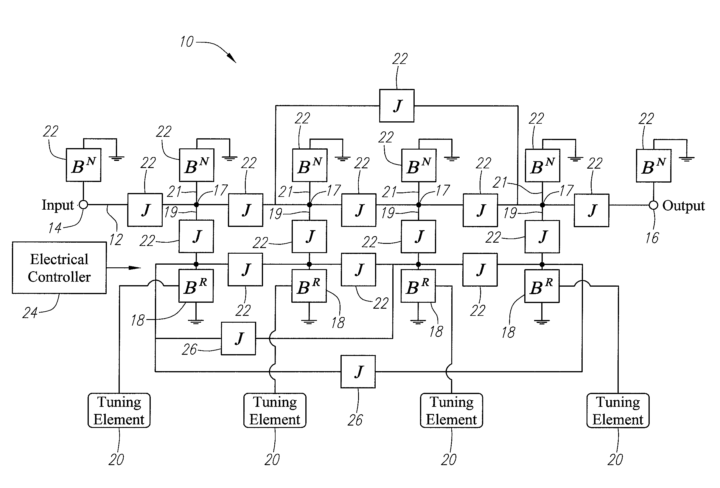
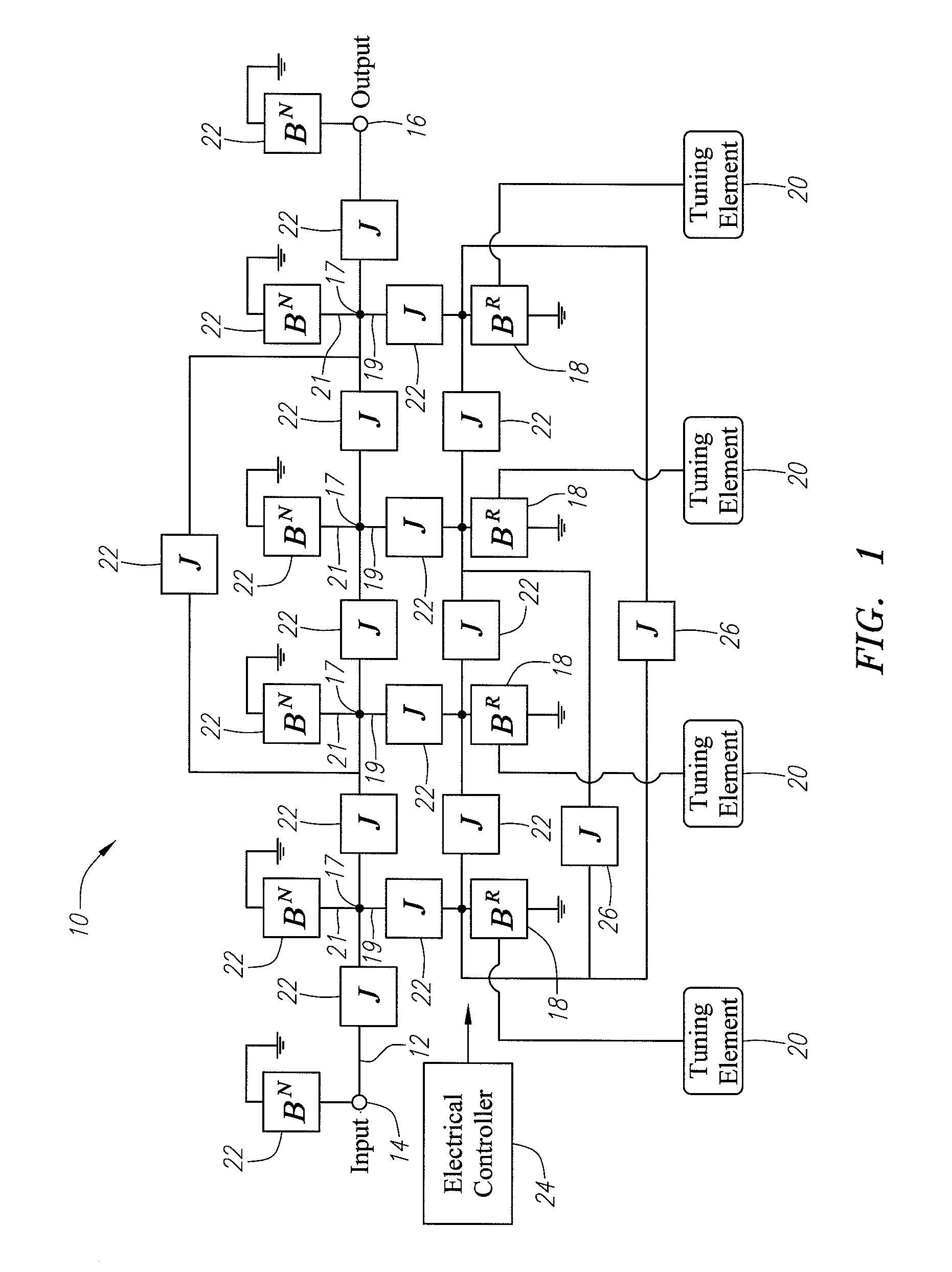
[0050]Referring to FIG. 1, a tunable radio frequency (RF) filter 10 constructed in accordance with the present inventions will now be described. In the illustrated embodiment, the RF filter 10 is a band-pass filter having pass band tunable within a desired frequency range, e.g., 800-900 MHz or 1,800-2,220 MHz. In a typical scenario, the RF filter 10 is placed within the front-end of a receiver (not shown) behind a wide pass band filter that rejects the energy outside of the desired frequency range. The RF filter 10 generally comprises a signal transmission path 12 having an input 14 and an output 16, a plurality of nodes 17 disposed along the signal transmission path 12, a plurality of resonant branches 19 respectively extending from the nodes 17, and a plurality of non-resonant branches 21 respectively extending from the nodes 17. The RF filter 10 further comprises a plurality of resonant elements 18 (in this case, four) between the input 14 and output 16, and in particular coupled...


PUM

PropertyMeasurementUnit
Frequencyaaaaaaaaaa
Superconductivityaaaaaaaaaa
Reflectionaaaaaaaaaa

Abstract

A tunable RF filter comprises a signal transmission path having an input and output, a plurality of resonant elements disposed along the signal transmission path between the input and output, and a set of non-resonant elements coupling the resonant elements together to form a stop band having a plurality of transmission zeroes corresponding to respective frequencies of the resonant elements, and at least one sub-band between the transmission zeroes. The set of non-resonant elements comprises a first plurality of non-resonant elements respectively coupled in parallel with the resonant elements, and a second plurality of non-resonant elements respectively coupled in series with the resonant elements. The first plurality of non-resonant elements comprises at least one variable non-resonant element for selectively introducing at least one reflection zero within the stop band to create a pass band in one of the one sub-band(s) without varying any of the second plurality of non-resonant elements.

Description

RELATED APPLICATION[0001]This application claims priority from U.S. Provisional Patent Application Ser. No. 60 / 937,462, filed Jun. 27, 2007, which is expressly incorporated herein by reference, and is a continuation-in-part of U.S. patent application Ser. No. 11 / 561,333.FIELD OF THE INVENTION[0002]The present inventions generally relate to microwave circuits, and in particular, microwave band-pass filters.BACKGROUND OF THE INVENTION[0003]Electrical filters have long been used in the processing of electrical signals. In particular, such electrical filters are used to select desired electrical signal frequencies from an input signal by passing the desired signal frequencies, while blocking or attenuating other undesirable electrical signal frequencies. Filters may be classified in some general categories that include low-pass filters, high-pass filters, band-pass filters, and band-stop filters, indicative of the type of frequencies that are selectively passed by the filter. Further, f...

Claims


Application Information

Patent Timeline
IPC IPC(8): H03H7/12
CPCH01P1/20336H03H7/0161H03H7/12H01P1/20H03H2210/012H03H7/0153H03H7/1791H03H7/075H03H7/1758H03H2007/013H03H7/54H03H2009/02204H03H2210/025H03H2210/033Y10T29/49018G06F30/30G06F30/36G06F30/367G06F30/392G06F30/394G06F2111/06G06F2111/10G06F2111/20G06F2119/10H03H3/00H03H9/46H03H9/462H03H9/542H03H9/64H03H9/171H03H7/06H03H9/465H03H9/6406
Inventor TSUZUKI, GENICHIWILLEMSEN, BALAM A.
Owner MURATA MFG CO LTD
Why Eureka
Try Eureka