Inkjet printhead with filter structure at inlet to ink chambers
What is Al technical title?
Al technical title is built by PatSnap Al team. It summarizes the technical point description of the patent document.
a filter structure and inkjet printing technology, applied in the field of inkjet printing heads, can solve the problems of reducing limiting the size of the nozzle array, so as to reduce limit the print speed, the effect of fast refilling time and reducing the volume of the ink chamber
Inactive Publication Date: 2008-12-18
SILVERBROOK RES PTY LTD
View PDF33 Cites 2 Cited by
Summary
Abstract
Description
Claims
Application Information
AI Technical Summary
This helps you quickly interpret patents by identifying the three key elements:
Problems solved by technology
Method used
Benefits of technology
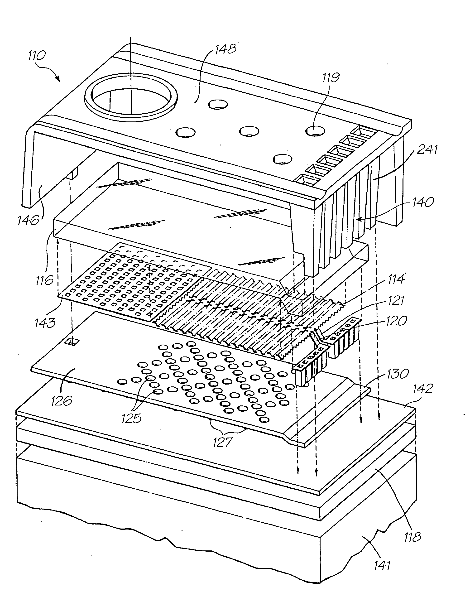
[0020]an array of droplet ejectors supported on a printhead integrated circuit (IC), each of the droplet ejectors has a nozzle aperture and an actuator for ejecting a droplet of ink through the nozzle aperture and, each of the droplet ejectors has a chamber in which the actuator is positioned, the chamber having an inlet for fluid communication with an ink supply, and a filter structure in the inlet to inhibit ingress of contaminants into the chamber.
[0056]Increasing the speed of the media substrate relative to the printhead, whether the printhead is a scanning or pagewidth type, reduces the time needed to complete printjobs.
Problems solved by technology
Accurate registration between the thermal actuators and the nozzles can be problematic.
These problems effectively restrict the size of the nozzle array in any one monolithic plate and corresponding actuator substrate.
Furthermore, differential thermal expansion between the nozzle plate and the actuator substrate create greater misalignments as the array sizes increase.
Given these limits on nozzle array size, pagewidth printheads using this two-part design are impractical.
The complexity of this arrangement makes such printers commercially unrealistic.
Each technology may have its own advantages and disadvantages in the areas of cost, speed, quality, reliability, power usage, simplicity of construction operation, durability and consumables.
Method used
Image
Click on the blue label to locate the original text in one second.
Reading with bidirectional positioning of images and text.
Examples
Embodiment Construction
IJ26
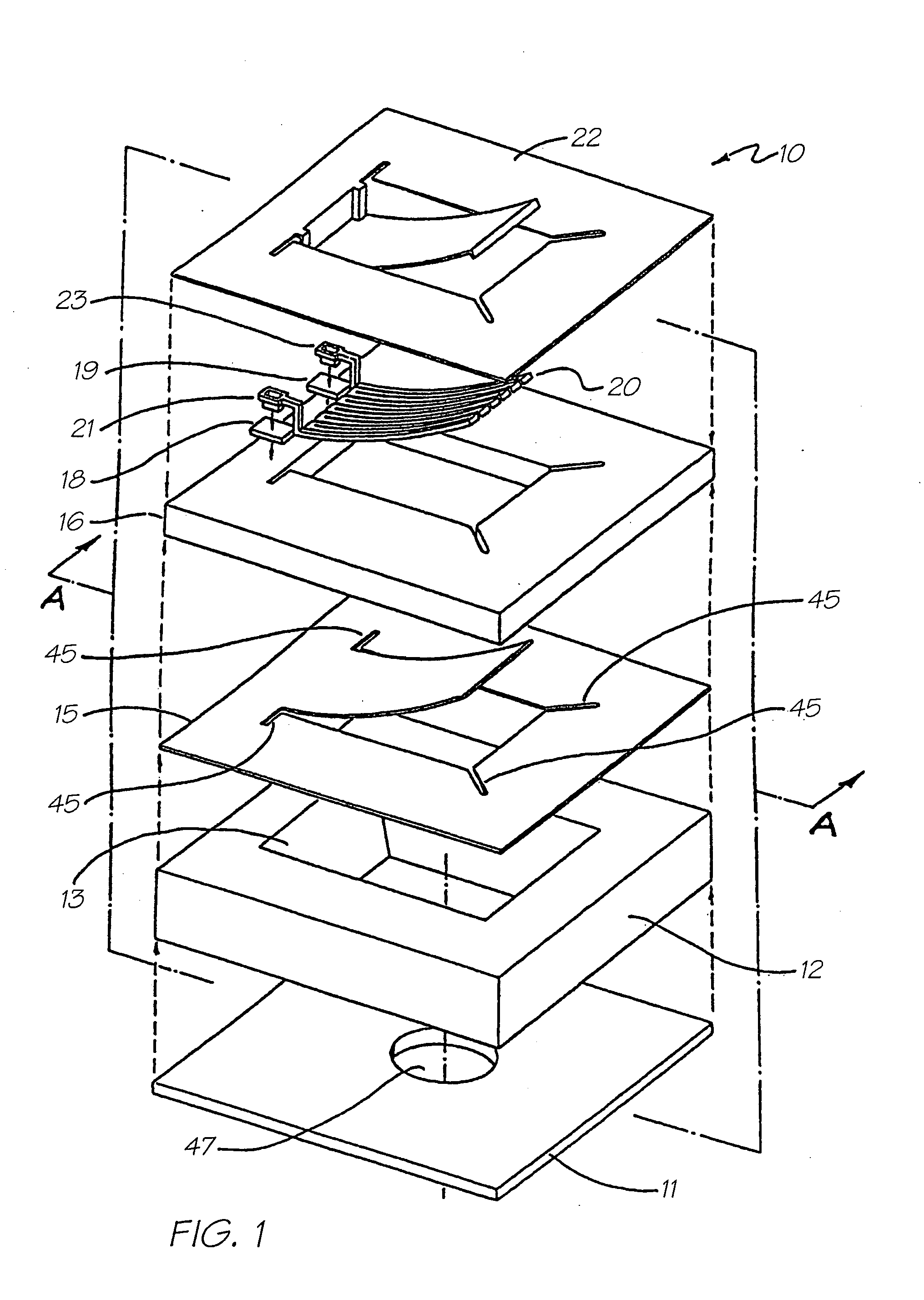
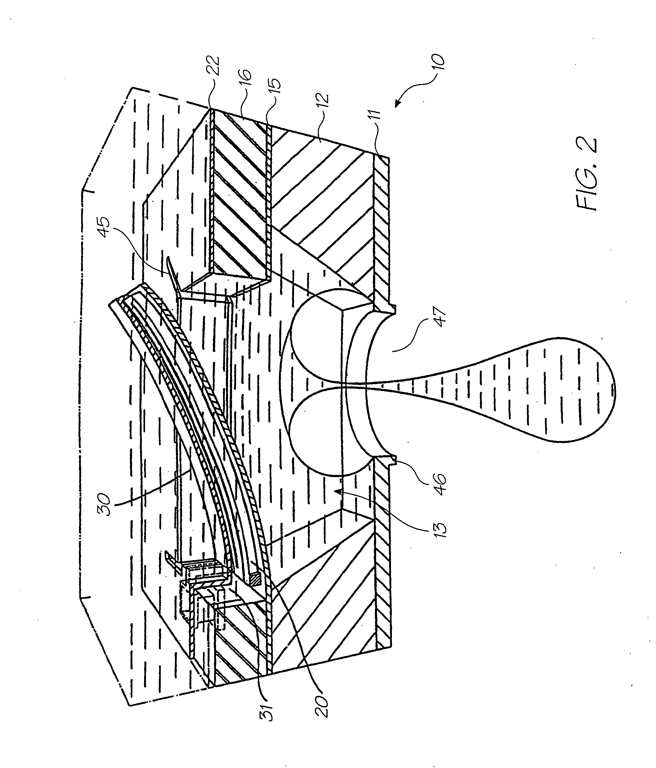
[0076]The embodiment shown in FIGS. 1 to 15 is referred to by the Applicant and within the Assignee company, as the IJ26 printhead. In this printhead, shape memory materials are utilized to construct an actuator suitable for injecting ink from the nozzle of an ink chamber.
[0077]FIG. 1 illustrates an exploded perspective view 10 of a single ink jet nozzle as constructed in accordance with the preferred embodiment. The ink jet nozzle 10 is constructed from a silicon wafer base utilizing back etching of the wafer to a boron doped epitaxial layer. Hence, the ink jet nozzle 10 comprises a lower layer 11 which is constructed from boron doped silicon. The boron doped silicon layer is also utilized a crystallographic etch stop layer. The next layer comprises the silicon layer 12 that includes a crystallographic pit 13 having side walls etched at the usual angle of 54.74 degrees. The layer 12 also includes the various required circuitry and transistors for example, CMOS layer (not shown)...
PUM
Property
Measurement
Unit
thick
aaaaa
aaaaa
thick
aaaaa
aaaaa
thick
aaaaa
aaaaa
Abstract
An inkjet printhead that has an array of droplet ejectors supported on a printhead integrated circuit (IC). Each of the droplet ejectors has a nozzle aperture and an actuator for ejecting a droplet of ink through the nozzle aperture. Each of the droplet ejectors has a chamber in which the actuator is positioned, the chamber having an inlet for fluid communication with an ink supply. A filter structure in positioned the inlet to inhibit ingress of contaminants into the chamber.
Description
CROSS REFERENCES TO RELATED APPLICATIONS[0001]The present application is a continuation in part of U.S. application Ser. No. 11 / 525,857 filed 25 Sep. 2006, which is in turn a continuation of U.S. application Ser. No. 11 / 064,011 filed on Feb. 24, 2005, now issued as U.S. Pat. No. 717,8903 which is a continuation of U.S. application Ser. No. 10 / 893,380 filed on Jul. 19, 2004, now issued U.S. Pat. No. 6,938,992, which is a continuation of U.S. application Ser. No. 10 / 307,348 filed on Dec. 2, 2002, now issued as U.S. Pat. No. 6,764,166, which is a continuation of U.S. application Ser. No. 09 / 113,122 filed on Jul. 10, 1998, now issued as U.S. Pat. No. 6,557,977, the entire contents of which are herein incorporated by reference.[0002]The following Australian provisional patent applications are hereby incorporated by reference. For the purposes of location and identification, US patents / patent applications identified by their US patent / patent application serial numbers (USSN) are listed al...
Claims
Application Information
Patent Timeline
Application Date:The date an application was filed.
Publication Date:The date a patent or application was officially published.
First Publication Date:The earliest publication date of a patent with the same application number.
Issue Date:Publication date of the patent grant document.
PCT Entry Date:The Entry date of PCT National Phase.
Estimated Expiry Date:The statutory expiry date of a patent right according to the Patent Law, and it is the longest term of protection that the patent right can achieve without the termination of the patent right due to other reasons(Term extension factor has been taken into account ).
Invalid Date:Actual expiry date is based on effective date or publication date of legal transaction data of invalid patent.
Patent Type & Authority Applications(United States)