
System and Method for Creating a Mirror Effect in a Liquid Crystal Display

a liquid crystal display and mirror effect technology, applied in non-linear optics, instruments, optics, etc., can solve the problems of loss of contrast, increase of ambient light contamination of video image on screen, and degrade of video image contras

Inactive Publication Date: 2008-12-18
TTE TECH INC
View PDF7 Cites 21 Cited by
  • Summary
  • Abstract
  • Description
  • Claims
  • Application Information

AI Technical Summary

Benefits of technology

[0009]The disclosed embodiments relate to a system and method for creating a mirror effect in a liquid crystal display. More specifically, in one embodiment, there is provided a display device comprising a first absorptive polarizer, a first liquid crystal arrayed adjacent to the first absorptive polarizer, a second absorptive polarizer arrayed adjacent to the first liquid crystal wherein the second absorptive polarizer is cross polarized with the first absorptive polarizer, a reflective polarizer arrayed adjacent to the second absorptive polarizer, a second liquid crystal arrayed adjacent to the reflective polarizer, and a third absorptive polarizer arrayed adjacent to the second liquid crystal, wherein the third absorptive polarizer is cross polarized with respect to the reflective polarizer.

Problems solved by technology

Although once limited mainly to use in place of cathode ray televisions, flat panel displays have recently begun to find uses in places where it is impractical to use a cathode ray television.
Unfortunately, conventional systems for creating a mirrored surface on a flat panel display have several disadvantages.
Foremost amongst these disadvantages is that adding a conventional mirrored surface to a flat panel display causes a loss of contrast when the flat panel television is used to display video images.
More specifically, as the reflectivity of a mirrored surface within the flat panel display increases, the amount of ambient light contamination of the video image on the screen increases.
Amongst other things, this increase in ambient light contamination can degrade the contrast of the video of the video image, especially with regard to darker colors, such as black.

Method used


Image

  • System and Method for Creating a Mirror Effect in a Liquid Crystal Display
  • System and Method for Creating a Mirror Effect in a Liquid Crystal Display
  • System and Method for Creating a Mirror Effect in a Liquid Crystal Display

Examples


Embodiment Construction

[0014]One or more specific embodiments of the present invention will be described below. In an effort to provide a concise description of these embodiments, not all features of an actual implementation are described in the specification. It should be appreciated that in the development of any such actual implementation, as in any engineering or design project, numerous implementation-specific decisions must be made to achieve the developers' specific goals, such as compliance with system-related and business-related constraints, which may vary from one implementation to another. Moreover, it should be appreciated that such a development effort might be complex and time consuming, but would nevertheless be a routine undertaking of design, fabrication, and manufacture for those of ordinary skill having the benefit of this disclosure.

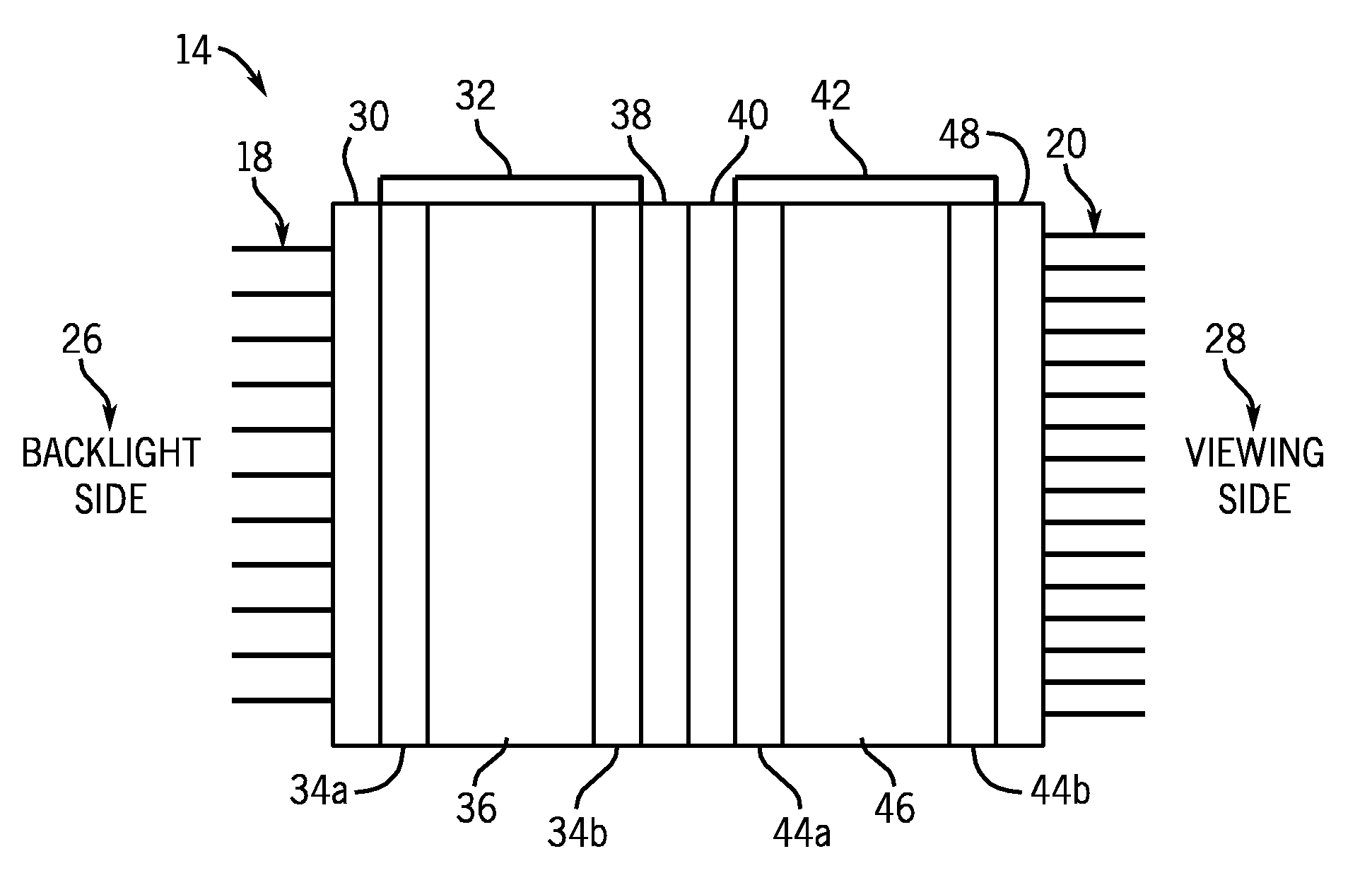
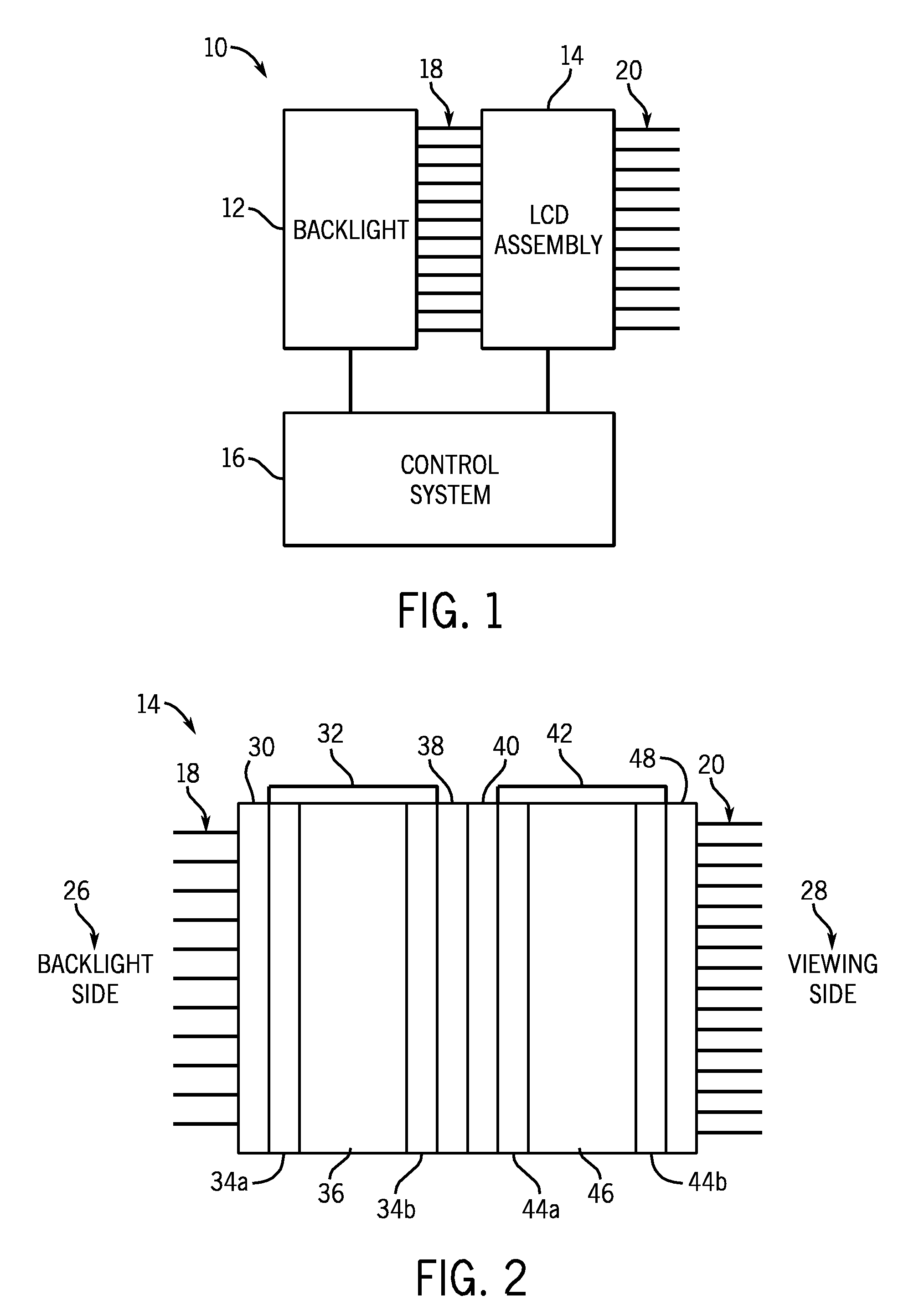
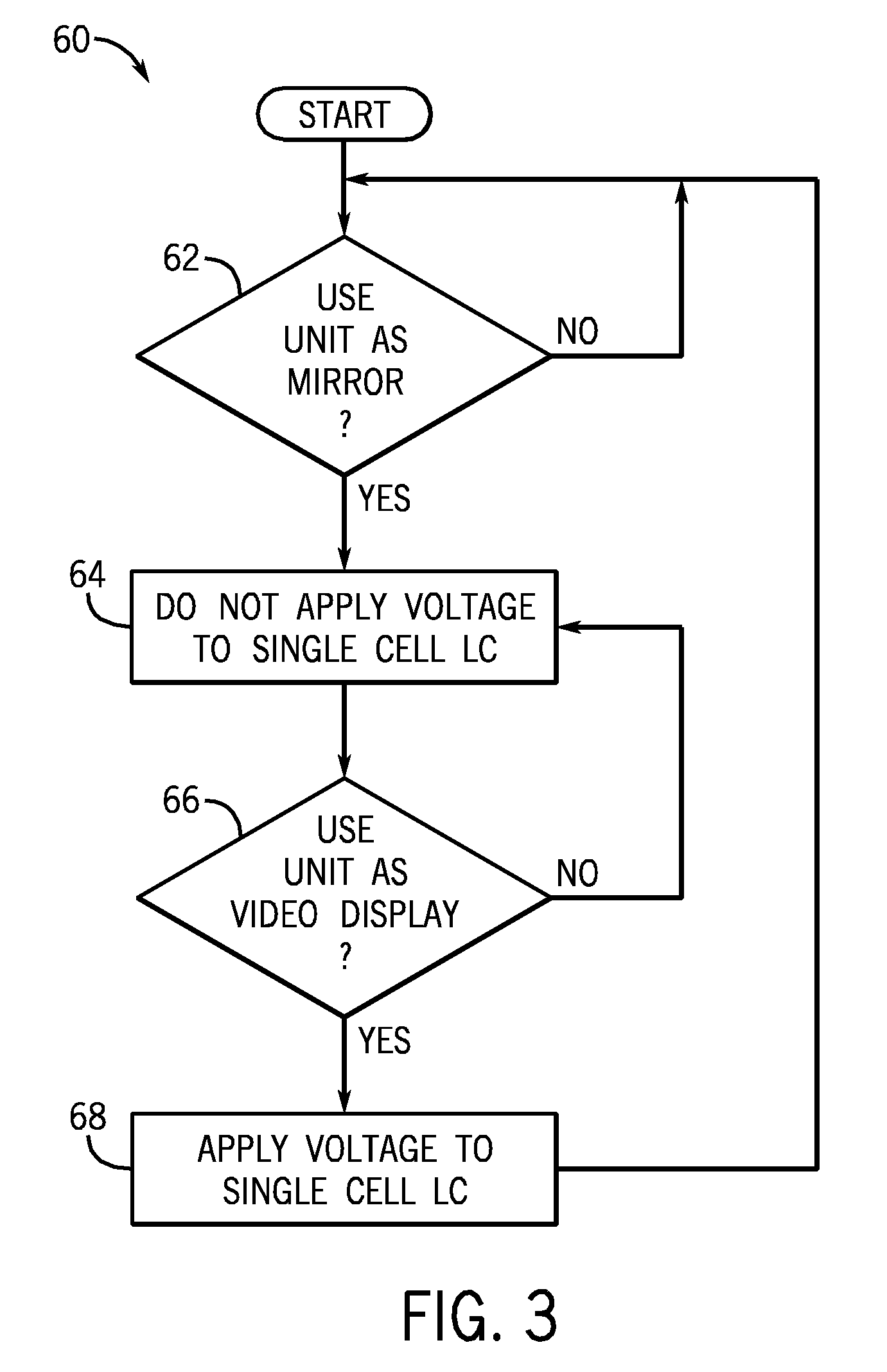
[0015]The embodiments described herein relate to a system and method for creating a mirror effect in a liquid crystal display (“LCD”). More specifically, ...


PUM

PropertyMeasurementUnit
thickaaaaaaaaaa
phase angleaaaaaaaaaa
switching voltagesaaaaaaaaaa

Abstract

The disclosed embodiments relate to a system and method for creating a mirror effect in a liquid crystal display. More specifically, in one embodiment, there is provided a display device comprising a first absorptive polarizer, a first liquid crystal arrayed adjacent to the first absorptive polarizer, a second absorptive polarizer arrayed adjacent to the first liquid crystal, wherein the second absorptive polarizer is cross polarized with the first absorptive polarizer, a reflective polarizer arrayed adjacent to the second absorptive polarizer, a second liquid crystal arrayed adjacent to the reflective polarizer, and a third absorptive polarizer arrayed adjacent to the second liquid crystal, wherein the third absorptive polarizer is cross polarized with respect to the reflective polarizer.

Description

FIELD OF THE INVENTION[0001]The present invention relates generally to liquid crystal displays (“LCDs”). More specifically, the present invention is related to a system and method for creating a mirror effect in an LCD.BACKGROUND OF THE INVENTION[0002]This section is intended to introduce the reader to various aspects of art, which may be related to various aspects of the present invention that are described and / or claimed below. This discussion is believed to be helpful in providing the reader with background information to facilitate a better understanding of the various aspects of the present invention. Accordingly, it should be understood that these statements are to be read in this light, and not as admissions of prior art.[0003]As most people are aware, liquid crystal displays (“LCDs”) are employed in a wide variety of electronic devices to display information, data, pictures, video, and so forth. One of the more popular uses for LCDs over the past few years has been in flat p...

Claims


Application Information

Patent Timeline
Patent Type & Authority Applications(United States)
IPC IPC(8): G02F1/1333G02F1/1335G02F1/13
CPCG02F1/133536G02F1/13471G02F2203/02
Inventor O'DONNELL, EUGENE MURPHY
Owner TTE TECH INC
Learn More