Clip on heat sink

a heat sink and clip technology, applied in the field of clip on heat sink, can solve the problems of increased power dissipation per square area, reduced device size, and higher clocking frequency

Inactive Publication Date: 2008-12-18
TELLABS BEDFORD
View PDF17 Cites 65 Cited by
  • Summary
  • Abstract
  • Description
  • Claims
  • Application Information

AI Technical Summary

Problems solved by technology

Along with this expanded functionality, the size of devices has diminished, resulting in higher clocking frequencies and increased power dissipation per square area.
Excessive heat may adversely affect the performance of the circuit, cause permanent degradation of its c

Method used


Image

  • Clip on heat sink
  • Clip on heat sink
  • Clip on heat sink

Examples


Embodiment Construction

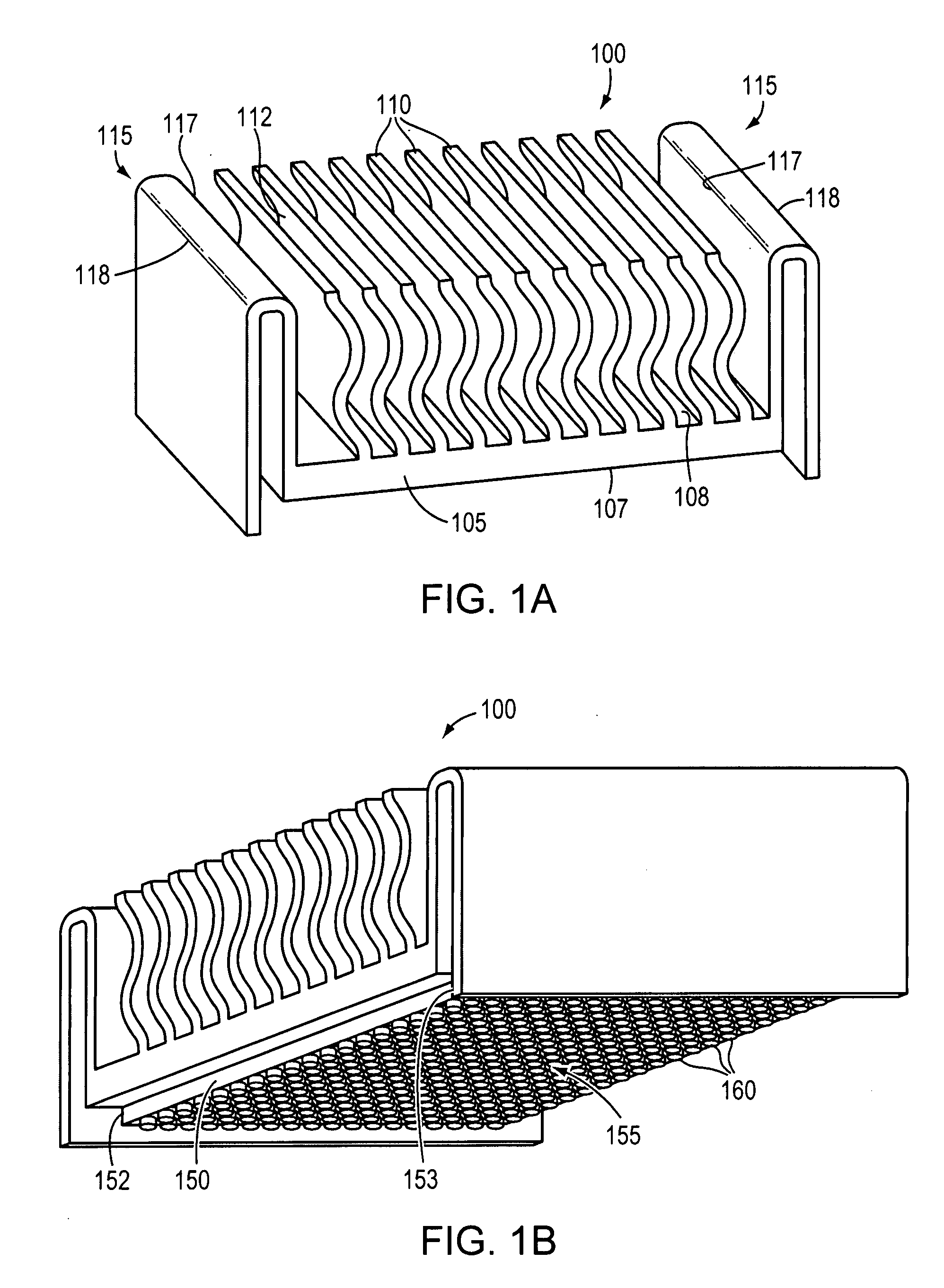
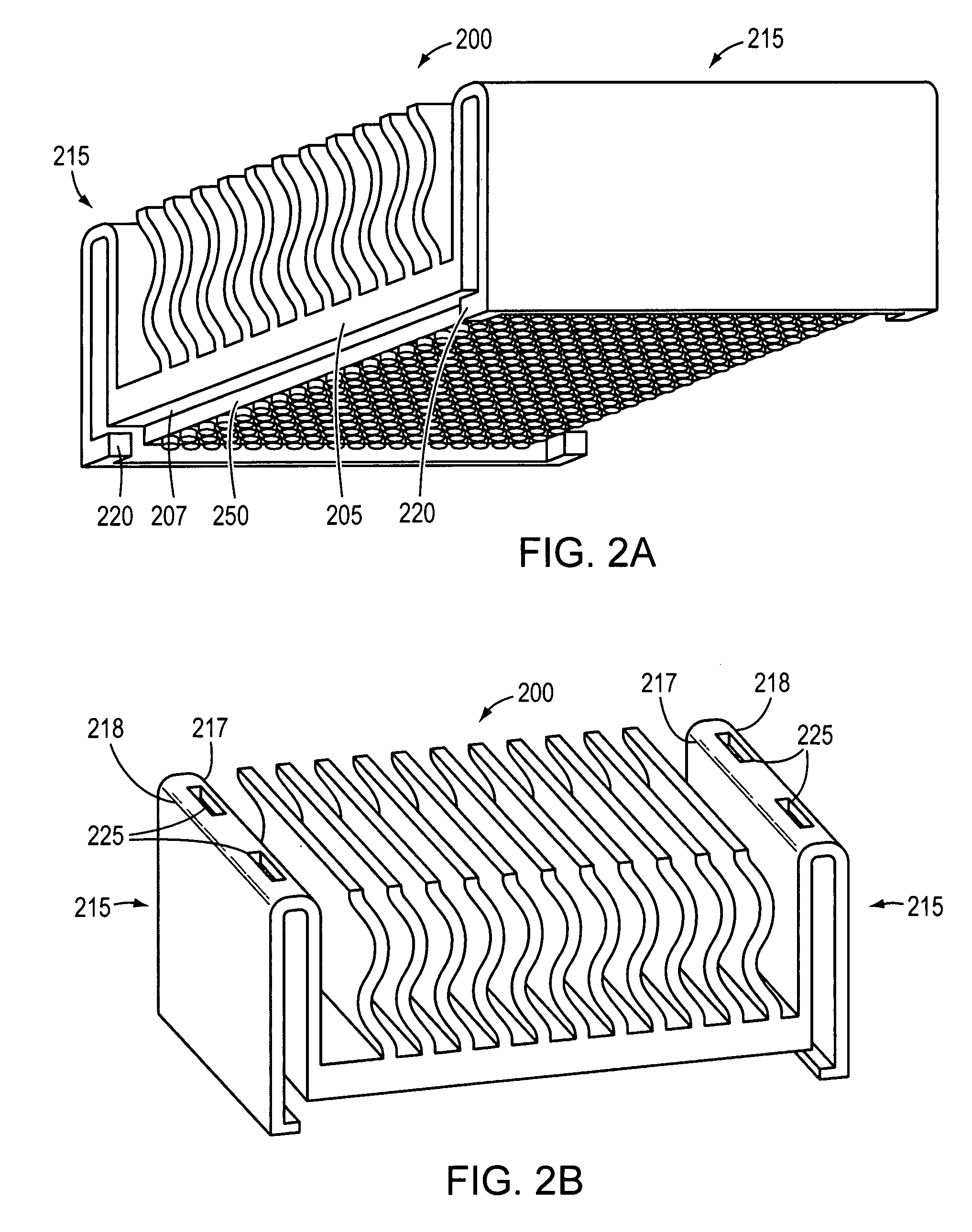
[0013]A description of example embodiments of the invention follows.

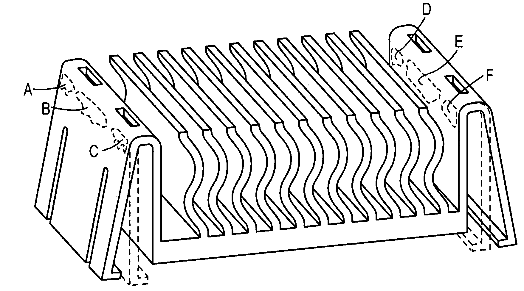
[0014]Conventional heat sinks and clips for their attachment are inefficient, expensive to produce and bulky. Conventional heat sinks typically include both a body and a fastener. That fastener may be a curved piece that applies pressure on an electronic component to which the heat sink is applied when installed. However, such fasteners reduce the available convection surface area of heat sinks, thereby reducing their efficiency. Other conventional heat sinks employ spring action for securing the body to the electronic component, but require special modification of the PCB. Further conventional heat sinks require screws, push pins, clips, anchors, or other forms of mechanical attachment that are additional parts beyond the body, itself, that take up valuable surface area on the PCB and block air flow to the convection surfaces of the heat.

[0015]Further, conventional methods of securing a heat sink to an integrated c...


PUM


Abstract

A heat sink according to an embodiment of the present invention can be attached to any device without printed circuit board (PCB) modification. The heat sink may clamp on device edges, which does not stress solder balls between the device and heat sink. The heat sink may be configured to be installed to or removed from the device without special tools. The heat sink may be extruded, machined, or die cast aluminum or other material to reduce part and tooling cost, and may be black anodized to be electrically non-conductive. A single-piece embodiment eliminates a need for a separate clip, thereby increasing heat transfer by as much as twenty-five percent or more over heat sinks employing clips. Further, wavy fins or other heat dissipation configurations may increase heat transfer by at least eleven percent, for a total heat transfer improvement of at least thirty-six percent over a two-part heat sink.

Description

BACKGROUND OF THE INVENTION[0001]As integrated circuit and similar technologies have improved, greater functionality has been incorporated into devices. Along with this expanded functionality, the size of devices has diminished, resulting in higher clocking frequencies and increased power dissipation per square area. As a consequence, today's integrated circuit devices generate more heat while possessing smaller surface areas to dissipate the heat. Therefore, it is useful to have a high rate of heat transfer from the integrated circuit package to maintain the temperature of the integrated circuit within safe operating limits. Excessive heat may adversely affect the performance of the circuit, cause permanent degradation of its components, and increase failure rates.[0002]A heat exchange with a heat sink may be used for transferring heat away from a heat source, such as an electronic component or printed circuit board (PCB), to maintain the component within an optimum operating tempe...

Claims


Application Information

Patent Timeline
IPC IPC(8): H05K7/20
CPCH01L23/367H01L23/4093H01L2924/0002H01L2924/00
Inventor GIACOMA, LAWRENCE M.
Owner TELLABS BEDFORD
Why Eureka
Try Eureka