Battery and Method for Producing the Same

Inactive Publication Date: 2008-12-18
E M W ENERGY CO LTD
5 Cites 9 Cited by

AI-Extracted Technical Summary

Problems solved by technology

In recent years, however, as a new paradigm, called ubiquitous Internet, has been introduced, a small size and easy-carrying electronic devices have been being developed in a further extensive and intensive way.
While these attempts provide to users a freedom of movement and convenience of use, a stable supply of power should be associated therewith and currently draws attentions as a technical challenge to be solved.
Furthermore, since it exhibits a nearly constant discharging characteristic until being exhausted, the zinc-air battery is considered an alternative for the mercury battery, of which use is restricted because it contains heavy metals.
In the case where the crimping pressure is increased in order to improve the precision of sealing, the above problem becomes worse.
In addition...

Benefits of technology

[0041]According to the invention, deformation of a can caused by can-crimping is prevented to improved reliability of contact between the can and an electrode (or MEA) and battery performance.
[0042]In addition, a cathode can and an anode can are not overlapped, thereby eliminating necessity of a separate gasket and thus simplifying the manufacturing process thereof.
[0043]Furthermore, the hermetical sealing of battery does not require can-crimping, thus enabling to fabricate various shapes of battery having a polygonal transversal cross-section, as well as a circular cross-se...

Abstract

Disclosed are a batter and a manufacturing method of the battery. The battery includes a first electrode, a second electrode, a first can electrically contacting the first electrode, a second can electrically contacting the second electrode, and a body. The first and second cans are fusion-bonded with the body to seal the battery. In addition, the manufacturing method includes the steps of fusion-bonding the first can with one end of the body and fusion-bonding the second can with the other end of the body. According to the invention, deformation by can-crimping does not occur. An efficient method of manufacturing a battery is provided, which can be applied to a polygonal button cell battery, in addition to a circular one. Further disclosed are a cylindrical zinc-air battery without leakage and a method of manufacturing the same. In the manufacturing method, a gap between both opposite end portions of a cathode membrane is filled with a resin and fusion-bonded, thus preventing leakage of zinc gel. Alternatively, both end portions of the cathode membrane are heated, pressurized or ultrasonic-radiated to be fusion-bonded, thereby preventing leakage of zinc gel. The invention provides a universal cylindrical zinc-air battery, which conforms to standard specifications.

Application Domain

Fuel and primary cellsSmall-sized cells cases/jackets +5

Technology Topic

ZincZinc–air battery +3

Image

  • Battery and Method for Producing the Same
  • Battery and Method for Producing the Same
  • Battery and Method for Producing the Same

Examples

  • Experimental program(1)

Example

[0064]Hereinafter, the preferred embodiments of the present invention will be described in detail with reference to the accompanying drawings.
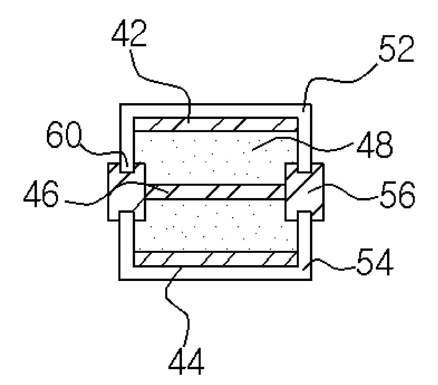
[0065]FIG. 6 is a sectional view of a button cell battery according to an embodiment of the invention.
[0066]The button cell battery of this embodiment includes a first can 52 and a second can 54 having a U-shape cross-section, and a body 56. Inserted inside of these are a first electrode 42 and a second electrode 44, a separator 46 for insulating them, and an electrolyte 48.
[0067]The first and second electrodes 42 and 44 are accommodated inside of the U-shape cans 52 and 54. The end portion 60 of the cans 52 and 54 is protruded higher than the electrodes 42 and 44. The first and second cans 52 and 54 are made of a conductive material and may be fabricated through a pressing process. The first electrode 42 is contacted with the first can 52 for electrons to be able to transfer and thus the first can 52 serves as an external terminal of the first electrode 42. Similarly, the second can 54 contacts the second electrode 44 to serve as an external terminal of the second electrode 44.
[0068]The separator 46 is made of a porous material to prevent the first and second electrodes 42 and 44 from being directly contacted with each other and at the same time allows electrons to be transferred through the electrolyte 48.
[0069]In this embodiment, hermetical sealing of the battery may be carried out by fusion-bonding of the cans 52 and 54 and the body 56. The body 56 is made of an insulation resin and insulates the first and second cans 52 and 54 from each other and also is fused at the end portion 60 of the cans 52 and 54 to seal the inside of the battery. The fusion-bonding of the body 56 and the cans 52 and 54 may be performed using ultrasonic, pressing, heating or the like, which will be hereafter described.
[0070]On the other hand, the shape of the end portion 60 of the cans 52 and 54 may be changed in order to improve reliability of the fusion-bonding.
[0071]FIG. 7 is an enlarged view of the fusion-bonded region of the first can and the body.
[0072]As illustrated in FIG. 7(a), a through-hole 62a may be formed at the end portion of the can 52, which is fusion-bonded with the body 56. In this case, the melted body 56 fills the inside of the through-hole 62a. Thus, after curing of the body 56, reliability of the bonding of the can 52 and the body 56 can be improved. In addition, as shown in FIGS. 7(b) and 7(c) respectively, a protrusion or a depression may be formed at the end portion of the can 52, thereby improving reliability for the bonding of the can 52 with the body 56.
[0073]Hereafter, referring to FIGS. 6 and 8, a manufacturing method of a button cell battery according to an embodiment of the invention will be explained. The method of this embodiment starts from step 100. At the step 100, a first electrode 42 is disposed on a first can 52 and a second electrode 44 is disposed on a second can 54 to thereby form an assembly of can and electrode. The electrodes 42 and 44 are accommodated inside of the cans 52 and 54 such that the end portion 60 of the cans 52 and 54 can be protruded.
[0074]Then, at step 110, the second can 54 is fusion-bonded to one end of the body 56. Referring to FIGS. 9 to 11, a method of fusion-bonding the second can 54 with the body 56 will be explained in details.
[0075]As illustrated in FIG. 9, the fusion-bonding of the second can 54 and the body 56 may be performed after the body 56 is first melted. Specifically, first, one end of the body 56 is melted (step 110a), and then the second can 54 is disposed at one end of the body 56 (step 110b). Although the body 56 generally is melted by heating, pressurization or ultrasonic radiation can be used. The melting method may be selected depending on the body 56 material.
[0076]Thereafter, the second can 54 is pressurized and the end portion of the can is inserted into the inside of the body 56 (step 110c). The body 56 is cooled and cured to fusion-bond the second can 54 and the body 56 (step 110d).
[0077]On the other hand, first, the second can 54 may be disposed at one end of the body 56, which is then heat-melted such that the end portion of the can 54 can be inserted into the body 56 by the weight of the can 54 and fusion-bonded thereto.
[0078]Alternatively, as shown in FIG. 10, the second can 54 is heated to carry out a fusion-bonding. In this case, the second can 54 is heated to a desired temperature (step 110e). Then, the second can 54 is disposed at one end of the body 56 and the end portion of the second can 54 is pressure-inserted inside of the body 56 (step 110f). At this step, the end portion of the can 54 melts the body 56 and simultaneously is inserted into inside of the body 56. Finally, the body 56 is cooled and cured to complete the fusion-bonding (step 110g). The heating temperature of the can 54 may be determined according to the melting temperature of the body 56, the inserting pressure, or the like.
[0079]As shown in FIG. 11, the fusion-bonding of the second can 54 and the body 56 may be performed through an in-mold forming process. Specifically, the second can 54 is inserted into a metallic mold (step 110h). An injection-molding space of the body 56 shape is formed in the metallic mold. Then, at step 110i, a resin is injected and the body 56 is injection-molded, thereby forming a fusion-bonded assembly of the body 56 and the second can 54.
[0080]Referring to FIG. 8 again, at step 120, a separator 46 is disposed at a space formed by the fusion-bonding of the body 56 and the second can 54 and an electrolyte 48 is filled. Finally, the first can 52 combined with the first electrode 42 is fusion-bonded to the other end of the body 56 to complete hermetical sealing of the battery (step 130). Fusion-bonding of the first can 52 and the body 56 may be carried out in the same way as in the second can 54 and the body 56, which is described above, in conjunction with FIGS. 9 to 11.
[0081]As described above, in this embodiment, without crimping the cans 52 and 54, they are fusion-bonded with the body 56 to seal the battery, thereby enabling to prevent deformation of a can, which occurs at the central portion of the cans 52 and 54 when they are bent or crimped. Therefore, reliability of contact between the can 52, 54 and the electrode 42, 44 can be improved and the battery performance can be enhanced.
[0082]In addition, as long as the cans 52 and 54 have a U-shaped cross-section, they may be manufactured in the form of a polygon as well as a circular. Thus, the present invention can be applied to manufacturing of polygonal button cell batteries and thus applications of the battery can be extended into a variety of fields.
[0083]In the above embodiments, the second can 54 is fusion-bonded before the first can 52, but the first can 52 may be first fusion-bonded or the first and second cans 52 and 54 may be simultaneously fusion-bonded.
[0084]Referring to FIG. 12, specifically, a method of manufacturing a button cell battery according to another embodiment of the invention will be explained. In this embodiment, in the same way as in FIG. 8, it starts with formation of an assembly of a can and electrode (Step 200). Then, a second can 54 is disposed at one end of the body 56 (step 210), and a separator 46 and an electrolyte 48 are inserted inside of the space formed by the body 56 and the second can 54 (step 220). Thereafter, at step 230, a first can is disposed at the other end of the body 56.
[0085]Finally, at step 240, both ends of the body 56 are melted and, after the end portions of the cans 52 and 54 are inserted into the inside of the body 56, the body 56 is cooled and cured to fusion-bond the body 56 with the cans 52 and 54. The fusion-bonding at the step 240 may be performed in various ways, which are previously described in conjunction with FIGS. 9 to 11.
[0086]In this embodiment, two cans are fusion-bonded at the same time. Thus, the manufacturing process can be simplified to thereby improve the efficiency of battery production.
[0087]The present invention may be applied to the manufacturing of a zinc-air battery.
[0088]FIG. 13 is a sectional view illustrating a button cell zinc-air battery according to another embodiment of the invention.
[0089]The zinc-air batter of this embodiment includes a cathode can 72 and an anode can 74 having U-shaped cross-sections, and a body 56. The cathode can 72 accommodates a membrane electrode assembly (MEA) 65, which is contacted with the cathode can 72. In addition, the inside of the battery is filled with a zinc gel 66 serving as an anode. The cathode can 72 and the anode can 74 are formed of a conductive material and can serve as a cathodic external terminal and an anodic external terminal respectively. On the other hand, the cathode can 72 is formed with a through-hole 68 such that the MEA 65 can be contacted with air.
[0090]In the zinc-air battery of this embodiment, the cathode can 72 and the anode can 74 are fusion-bonded to the body 56 to thereby seal the battery. The fusion-bonding of the body 56 with the cathode can 72 and the anode can 74 is carried out in the same way as in the previous embodiments of FIGS. 6 and 7 and thus details thereon will not be repeated here.
[0091]Hereafter, a manufacturing method of a button cell zinc-air battery according to yet another embodiment of the invention will be explained, referring to FIGS. 13 and 14.
[0092]According to this embodiment, at step 300, an anode can 74 is fusion-bonded to one end of the body 56. The fusion-bonding of the anode can 74 and the body 56 may be carried out in various ways, which are previously explained in conjunction with FIG. 7.
[0093]Thereafter, a zinc gel 66 is filled in the internal space formed by the assembly of the anode can 74 and the body 56 (step 310). The fusion-bonding of the body 56 and the anode can 74 seals the fusion area of them, thereby preventing leakage of the zinc gel 66.
[0094]At step 320, a cathode can 72 is fusion-bonded to the other end of the body 56. The cathode can 72 is pre-assembled with an MEA 65, or an anode membrane and a separator, and the end portion 60 of the cathode can 72 is protruded higher than the MEA 65. In this step, the end portion 60 of the protruded cathode can 72 is fusion-bonded to the other end of the body 56. The fusion-bonding of the cathode can 72 and the body 56 may be performed in various ways, which are previously explained in conjunction with FIGS. 9 to 11. In this way, the fusion-bonding of the cathode can 72 and the body 56 completes hermetical sealing of the battery.
[0095]In this embodiment, the anode can 74 and the cathode can 72 are fusion-bonded with the body 56 in the described order, but the cathode can 72 may be first fusion-bonded. In addition, the anode can 74 and the cathode can 72 may be simultaneously fusion-bonded. In this case, similar to the previous embodiment described in conjunction with FIG. 12, after completion of the disposition of cans 72 and 74 and filling of zinc gel 66, the cans 71 and 74 and the body are fusion-bonded to seal the battery.
[0096]In this embodiment, without crimping the cans 72 and 74, they are fusion-bonded with the body 56 to seal the battery, thereby enabling to prevent deformation of a can, which occurs when they are bent or crimped. Therefore, the battery performance can be improved. In addition, a polygonal can can be used to thereby enable to manufacture a polygonal button cell battery, as well as a circular one. Thus, application range for the zinc-are battery can be extended, beyond that of the circular button cell. In particular, besides a button cell battery, in case where the present invention is extensively applied to a standard battery type such as a cylindrical shape, a square pillar shape and the like, universal application of a zinc-air battery is possible.
[0097]Hereafter, a cylindrical zinc-air battery will be explained in greater detail.
[0098]FIG. 15 is a transversal cross-section of a cylindrical zinc-air battery according to another embodiment of the invention.
[0099]The cylindrical zinc-air battery of this embodiment includes a zinc-gel 66, a separator 46 capturing the zinc gel 66, a membrane 64 serving as a cathode membrane. The membrane 64 may be enclosed with an insulator 78 and a housing 80.
[0100]The housing 80 may be a metallic plate fabricated through a press forming and protects the battery and holds the outer appearance. In addition, the housing 80 may be connected with the membrane 64 (which is a cathode) at the upper portion (not shown) of the battery and thus serve as a cathode can supplying electrons to the membrane 64. The insulator 78 is provided for insulating between the housing 80 and the membrane 64 to prevent current leakage. The insulator 78 may be fabricated by means of an injection molding process using a resin. On the other hand, an opening 84 is formed in the housing 80 and the insulator 78 for oxygen to be supplied to the membrane 64, which is a cathode.
[0101]The membrane 64 and the separator 46 may be fabricated in a plane form and then bent into a cylindrical form to enable to capture the zinc gel 66. Both end portions of the bent membrane 64 and the separator 46 face each other with a gap in-between, and are bonded with each other by means of a bonding member 82. The bonding member 82 is made of a resin and fusion-bonded to the membrane 64 and the separator 46, so that leakage of the zinc gel can be prevented at the bonding area of the both end portions. In addition, as illustrated, the bonding member 82 is formed in such a way to cover part of the membrane 64 and the separator 46, thereby further improving its sealing effect.
[0102]Hereafter, referring to FIGS. 15 to 17, a method of manufacturing a cylindrical zinc-air battery according to another embodiment of the invention will be explained.
[0103]First, a cylindrical insulator 78 is prepared. The insulator 78 may be fabricated in the form of a cylinder using an injection molding process.
[0104]Then, a membrane 64 and a separator 46 having plane forms are prepared. As illustrated in FIG. 16, the separator 46 and the membrane 64 are disposed in a metallic mold 86 for injection molding in such a way that both end portions thereof face each other with a gap in-between. The metallic mold 86 forms a space 88 such that a resin is injected only around the gap of the membrane 64 and the separator 46. It is not necessary that the metallic mold accommodates the entirety of the membrane 64 and the separator 46. It may accommodate bonding area thereof.
[0105]Thereafter, as illustrated in FIG. 17, a resin is injected into the space 88 and the membrane 64 and the separator 46 are fusion-bonded to form the bonding member 82. At this time, the resin may be formed in such a manner to cover part of the membrane 64 and the separator 46. In addition, a prominence-and-depression or an opening is formed in the surface of both end portions of the membrane 64 and the separator 46, which contact with the resin, thereby allowing an easy fusion-bonding of resin. The resin is fusion-bonded with the membrane 64 and the separator 46 and thus internal space can be sealed and, in case where a zinc gel 66 is filled, leakage therefor can be prevented.
[0106]A zinc gel 66 is filled inside of the above-formed cylindrical membrane 64 and the separator 46, which is then inserted inside of the insulator 78. Finally, a housing is formed so as to coat the insulator 78 to thereby complete the manufacturing of a cylindrical zinc-air batter.
[0107]Hereafter, referring to FIG. 18, a cylindrical zinc-air battery according to another embodiment of the invention will be explained.
[0108]FIG. 18 is a transversal cross-section of a cylindrical zinc-air battery according to another embodiment of the invention.
[0109]In this embodiment, the same elements as in the previous embodiment are denoted by the same reference numerals and details thereon will not be repeated.
[0110]The cylindrical zinc-air battery of this embodiment includes a zinc gel, a separator capturing the zinc gel 66, and a membrane 64 serving as a cathode membrane. The membrane 64 may be wrapped around by an insulator 78 and a housing 80. In addition, an opening 84 may be formed in the housing 80 and the insulator 78 for air to come in and out.
[0111]The membrane 64 and the separator 46 may be formed in a plane form and then bent into the form of a cylinder so as to capture the zinc gel 66. At this time, both end portions of the bent membrane 64 and separator 46 are overlapped. In this case, as illustrated in FIG. 18, the both end portions may have slant faces inclined in opposite directions to each other to thereby so that they can be naturally overlapped and the thickness is not increased after being overlapped. The shape of the both end portion is not limited to the slant faces, but may take various other shapes as long as they have a complementary shape, for example, a protrusion in one face and a depression in the other face. The overlapped both end portions 70 may be fusion-bonded through heating, pressurizing or ultrasonic radiation. Thus, the zinc gel is prevented from being leaked through bonding area of the membrane 64 and the separator 46. On the other hand, although the membrane 64 and the separator 46 are illustrated as having a continuous slant face, they may have different shapes respectively to improve their sealing effects after bonding.
[0112]Then, referring to FIGS. 18 and 19, a method of manufacturing a cylindrical zinc-air battery according to another embodiment of the invention will be explained.
[0113]Firstly, a cylindrical insulator 78 is prepared and a membrane 64 and a separator 46 having plane shapes are prepared. Then, as illustrated in FIG. 19, the separator 46 and the membrane 64 are disposed in a jig 90 in such a way that its end portions are overlapped. The jig 90 can accommodate only the bonding area of the membrane 64 and the separator 46, not their entirety.
[0114]Thereafter, the overlapped both end portions 70 are fusion-bonded by means of heating, pressurizing or ultrasonic radiation through the jig 90. In this way, the both end portions of the membrane 64 and the separator 46 are fusion-bonded to each other to enable to seal the internal space thereof, and thus, in case where a zinc gel 66 is filled, leakage of the zinc gel 66 can be prevented.
[0115]A zinc gel 66 is filled inside of the above formed cylindrical membrane 64 and separator 46, which are then inserted into the inside of an insulator 78. Finally, a housing 80 is formed so as to coat the insulator 78 to complete manufacturing of a cylindrical zinc-air battery.
[0116]Although the present invention has been described with reference to several preferred embodiments, the description is illustrative of the invention and is not to be construed as limiting the invention. Various modifications and variations may occur to those skilled in the art, without departing from the scope of the invention as defined by the appended claims.
[0117]For example, in the batteries of the above embodiments, the separator 46 and the membrane 64 are illustrated as separate elements, but they may be embodied as a single element. In particular, according to the invention, these elements may be replaced by a membrane-electrode assembly (MEA). The MEA is a composite serving as a conventional cathode membrane and separator, which is well known in the art. Of course, instead of the MEA, a cathode membrane and a separator can be employed as separate elements, which is included in the scope of the invention as appreciated to those skilled in the art. In addition, each element of the invention may be made of one of well-known materials, from which those skilled in the art will be able to easily select the most suitable one.
[0118]In addition, in the manufacturing method of the above embodiments, individual process steps have been described in a particular order. However, it should be appreciated to those skilled in the art that these steps may be performed in a different order, without departing from the scope of the invention.
[0119]Furthermore, although in the embodiments of the invention, only essential elements related to the battery functions have been explained, in order to improve the functions of a battery, various well-known other elements may be added. For example, various functional membranes, such as a water-repellent membrane or a diffusion membrane, may be interposed between the membrane and the cathode can of a zinc-air battery.
[0120]Although the present invention has been described with reference to several preferred embodiments shown in figures, the description is just illustrative of the invention and various modifications and variations may occur to those skilled in the art.

PUM

PropertyMeasurementUnit
Pressure
Shape

Description & Claims & Application Information

We can also present the details of the Description, Claims and Application information to help users get a comprehensive understanding of the technical details of the patent, such as background art, summary of invention, brief description of drawings, description of embodiments, and other original content. On the other hand, users can also determine the specific scope of protection of the technology through the list of claims; as well as understand the changes in the life cycle of the technology with the presentation of the patent timeline. Login to view more.

Similar technology patents

Discharge lamp

InactiveUS20080191599A1deformation of be efficiently preventprevent deformation
Owner:PANASONIC CORP

Door panel

Owner:SHIN CATERPILLAR MITSUBISHI LTD CORP

Classification and recommendation of technical efficacy words

  • improve contact reliability
  • prevent deformation

Mobile terminal

InactiveCN106887695AImprove contact reliabilityReduce the difficulty of assembly
Owner:JRD COMM

Electrical connector

InactiveUS20070054556A1improve contact reliabilityimprove workability
Owner:HIROSE ELECTRIC GROUP

Multidirectional dual-line RJ45 lightning preventing network information module

InactiveCN104716523AEnhanced wire contact areaImprove contact reliability
Owner:胡清桂

Wire spring electric connector

InactiveCN1424792AImprove contact reliabilityreliable electrical contact
Owner:NR ENG CO LTD +1

DC contactor

InactiveCN110970269AImprove contact reliability
Owner:中泰福安(东莞)电子科技有限公司

Optical scanning device

Owner:MITSUMI ELECTRIC CO LTD

Image sensor with enlarged outward appearance of microlens and method for fabricating the same

ActiveUS20060023313A1prevent deformationsuperior step coverage characteristic
Owner:INTELLECTUAL VENTURES II

Blade sharpening system and method of using the same

ActiveUS20140179201A1prevent deformationunnecessary heating be prevent
Owner:AIGUISAGE ELITE
Why Eureka
Try Eureka