Self Sealing Cannula / Aperture Closure Cannula

a cannula and aperture technology, applied in the field of self sealing cannula/aperture closure cannula, can solve the problems of inability to control the loss of intraocular pressure during instrument exchange or removal, the height of the projection on the eye surface, and the trauma of the eye at the incision si

Inactive Publication Date: 2008-12-18
ALCON INC
View PDF14 Cites 20 Cited by
  • Summary
  • Abstract
  • Description
  • Claims
  • Application Information

AI Technical Summary

Benefits of technology

[0008]A further objective of the present invention is to provide a cannula

Problems solved by technology

This repeated removal and insertion can cause trauma to the eye at the incision site.
Disadvantages of prior art cannulae include the height of the projection on the surface of the eye, as well as the lack of any means to control loss of

Method used


Image

  • Self Sealing Cannula / Aperture Closure Cannula
  • Self Sealing Cannula / Aperture Closure Cannula
  • Self Sealing Cannula / Aperture Closure Cannula

Examples


Embodiment Construction

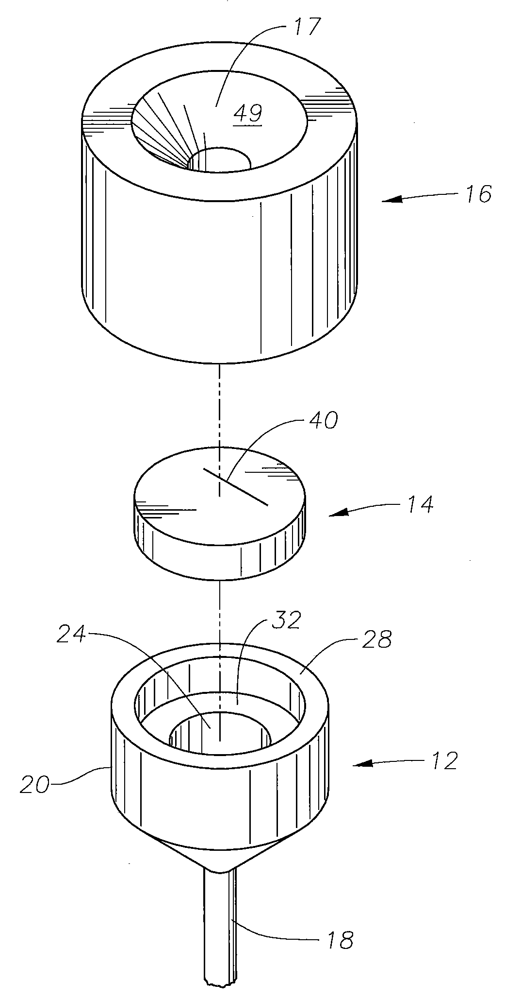
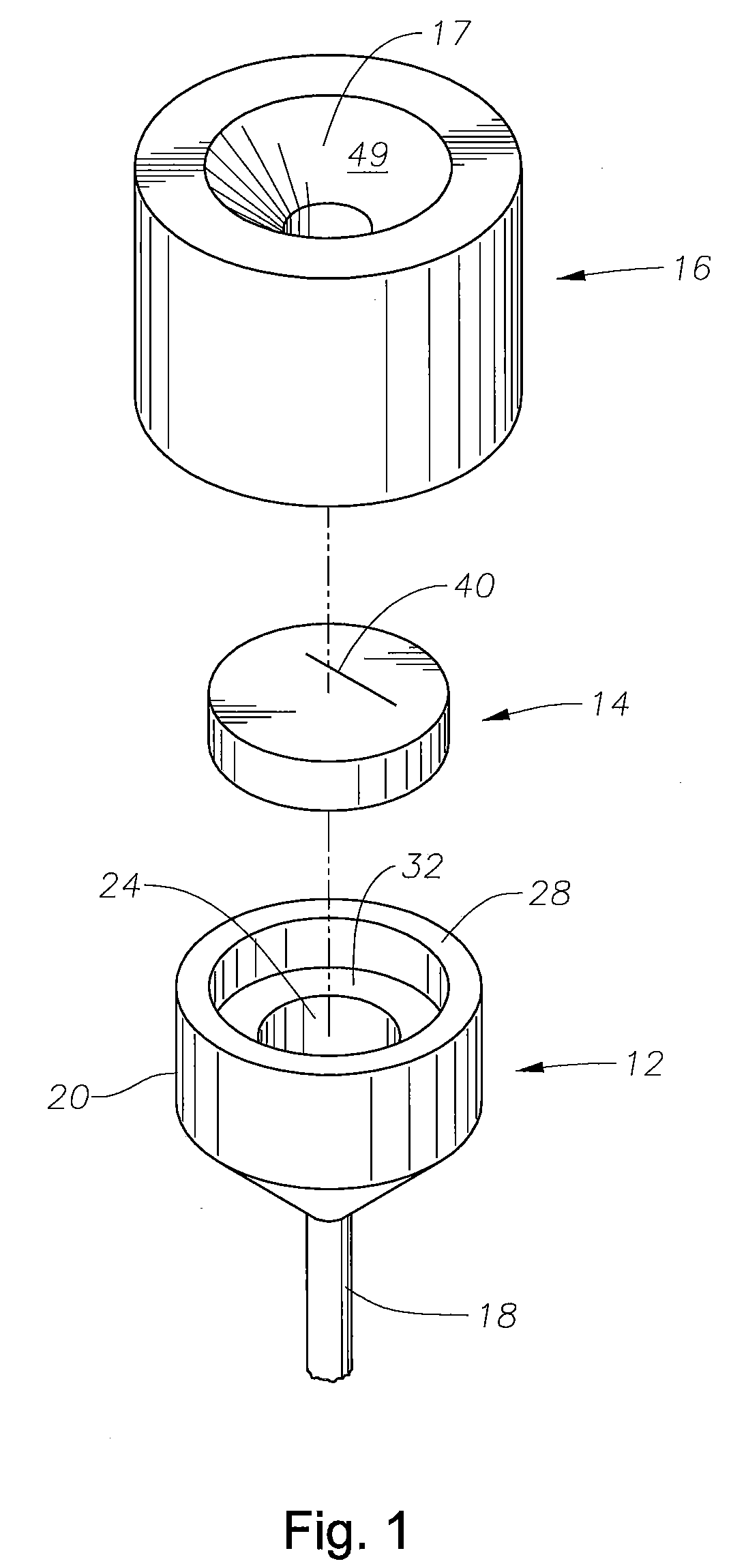
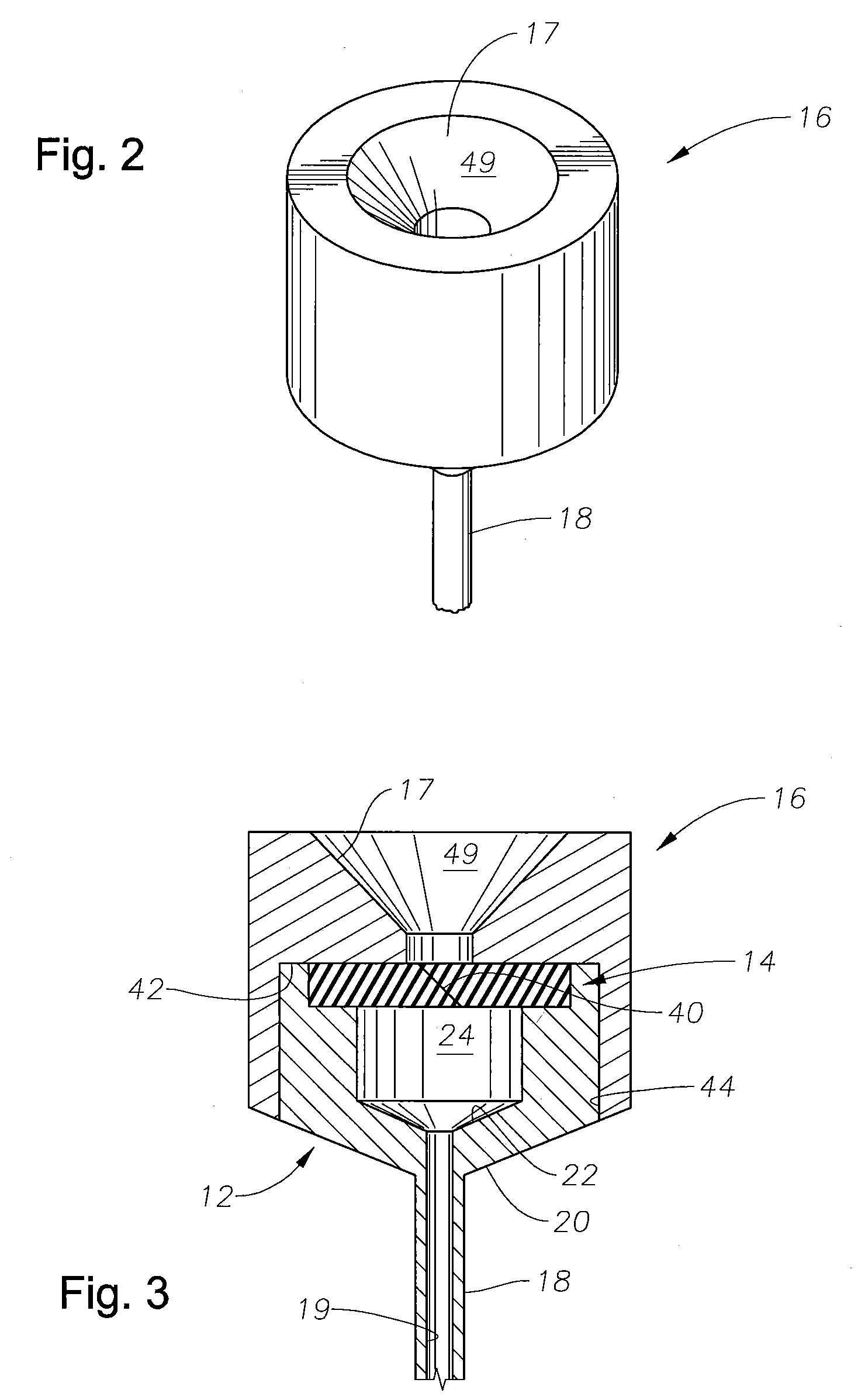
[0017]As best seen in FIGS. 1 through 4, cannula 10 generally consists of body 12, sealing disc 14, and cap 16. Body 12 and cap 16 may be made from any suitable material, such as stainless steel, titanium, or thermoplastic. Body 12 is comprised of tube 18 and hub 20 which may be formed integrally or in separate pieces. Tube 18 is of sufficient length to extend through sclera 130 and enter posterior chamber 140. Hub 20 is generally cylindrical with internal cavity 24 having distal floor 22 sloped or tapered at an angle of between about 18-24 degrees (most preferably about 22 degrees) so as to have a funnel shape directed toward bore 19 in tube 18. Cavity 24 may have a diameter of between about 0.040-0.050 inches (most preferably about 0.046 inches) or any other suitable diameter. Cavity 24 generally extends from proximal face 28 to distal floor 22 a depth of between about 0.025-0.035 inches (most preferably about 0.029 inches). Proximal face 28 of hub 20 is generally flat with circum...


PUM


Abstract

A cannula having a body, a sealing disc, and a cap. The sealing disc is located within the body and is compressed by the cap. An angled cut in the sealing disc allows microsurgical instruments to be inserted through the cannula into the eye. Upon removal, the cut in the sealing disc closes, preventing the loss of intraocular pressure.

Description

[0001]This invention relates to ophthalmic surgical equipment and more particularly to posterior segment ophthalmic surgical equipment.BACKGROUND OF THE INVENTION[0002]Microsurgical instruments typically are used by surgeons for removal of tissue from delicate and restricted spaces in the human body, particularly in surgery on the eye, and more particularly in procedures for removal of the vitreous body, blood, scar tissue, or the crystalline lens. Such instruments include a control console and a surgical handpiece with which the surgeon dissects and removes the tissue. With respect to posterior segment surgery, the handpiece may be a vitreous cutter probe, a laser probe, or an ultrasonic fragmenter for cutting or fragmenting the tissue and is connected to the control console by a long air-pressure (pneumatic) line and / or power cable, optical cable, or flexible tubes for supplying an infusion fluid to the surgical site and for withdrawing or aspirating fluid and cut / fragmented tissu...

Claims


Application Information

Patent Timeline
IPC IPC(8): A61F9/007
CPCA61B17/3462A61F9/00736
Inventor HICKINGBOTHAM, DYSON W.
Owner ALCON INC
Why Eureka
Try Eureka