Anterior Spinal Fusion and Fixation Cage with Integrated Plate and Method of Use

a technology of fixation cage and anterior spinal bone, which is applied in the field of implantable devices, can solve the problems of stress-induced failure, disadvantages of the procedure, and excessive blood loss

Inactive Publication Date: 2008-12-18
ABERNATHIE DENNIS LEE
View PDF9 Cites 152 Cited by
  • Summary
  • Abstract
  • Description
  • Claims
  • Application Information

AI Technical Summary

Problems solved by technology

The ALIF approach is common and well established; however, this procedure suffers from disadvantages due to current implant design.
This procedure is performed in close proximity to the large blood vessels that supply the legs, thereby risking damage to these blood vessels, which can result in excessive blood loss.
Anterior cages also are at risk for further migration into the disc space potentially causing complications.
This surface area reduction can lead to stress-induced failure such as subsidence or abnormal bone remodeling.
This problem is often compound

Method used


Image

  • Anterior Spinal Fusion and Fixation Cage with Integrated Plate and Method of Use
  • Anterior Spinal Fusion and Fixation Cage with Integrated Plate and Method of Use
  • Anterior Spinal Fusion and Fixation Cage with Integrated Plate and Method of Use

Examples


Embodiment Construction

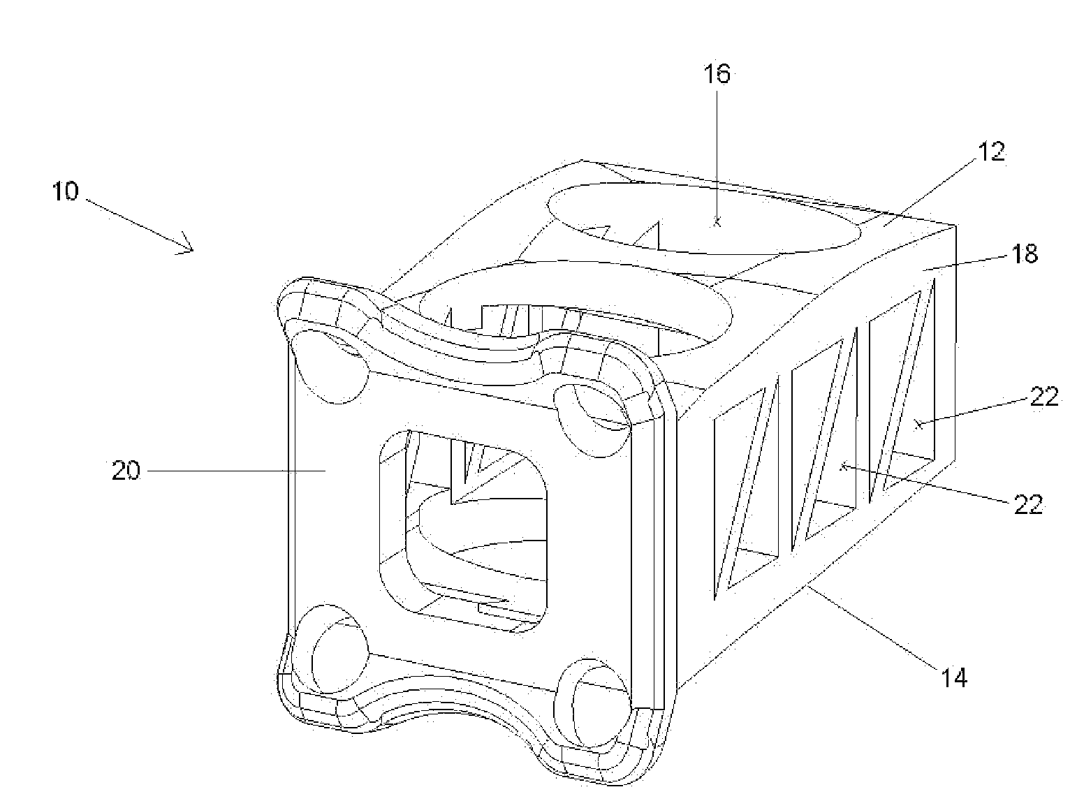
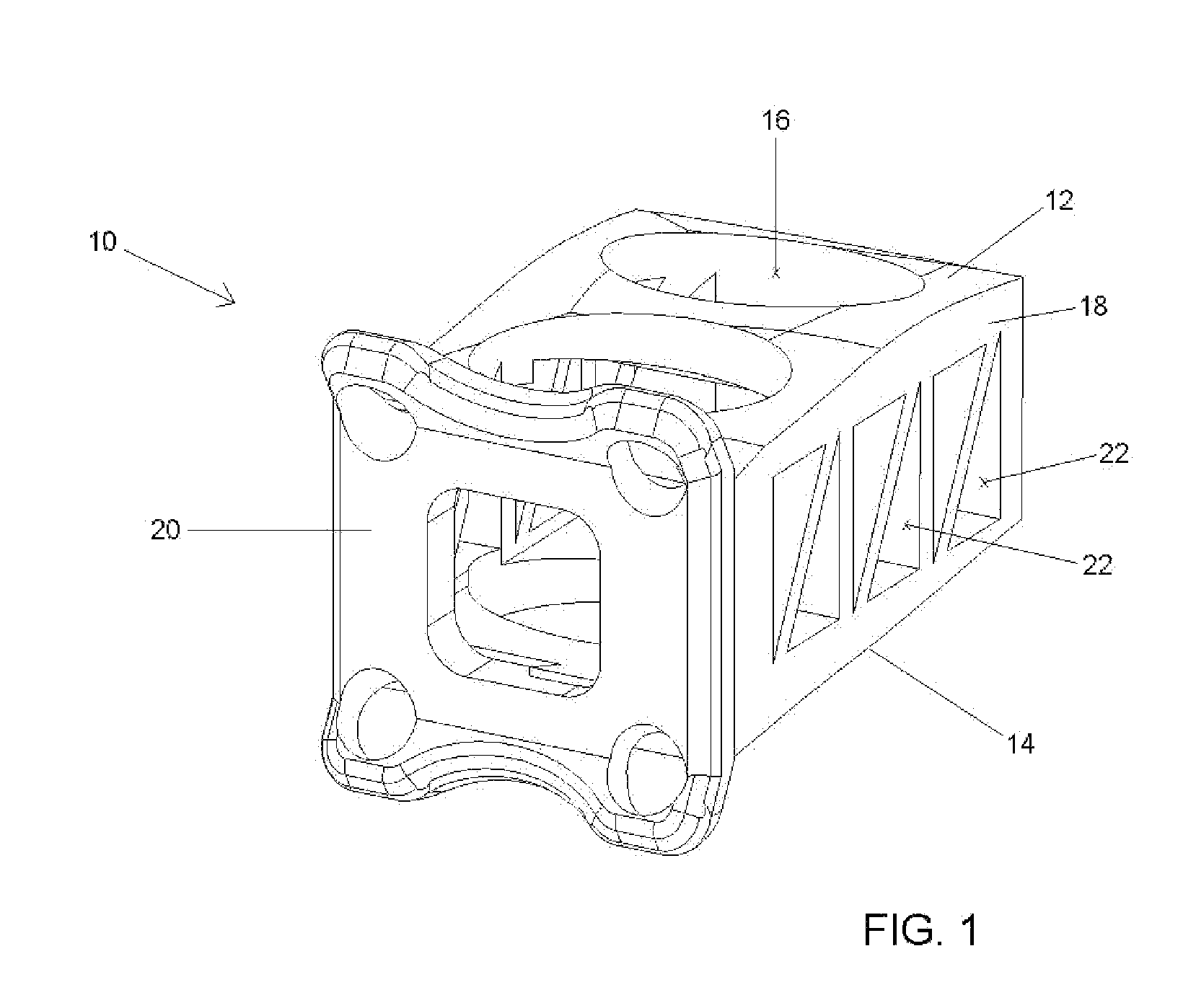
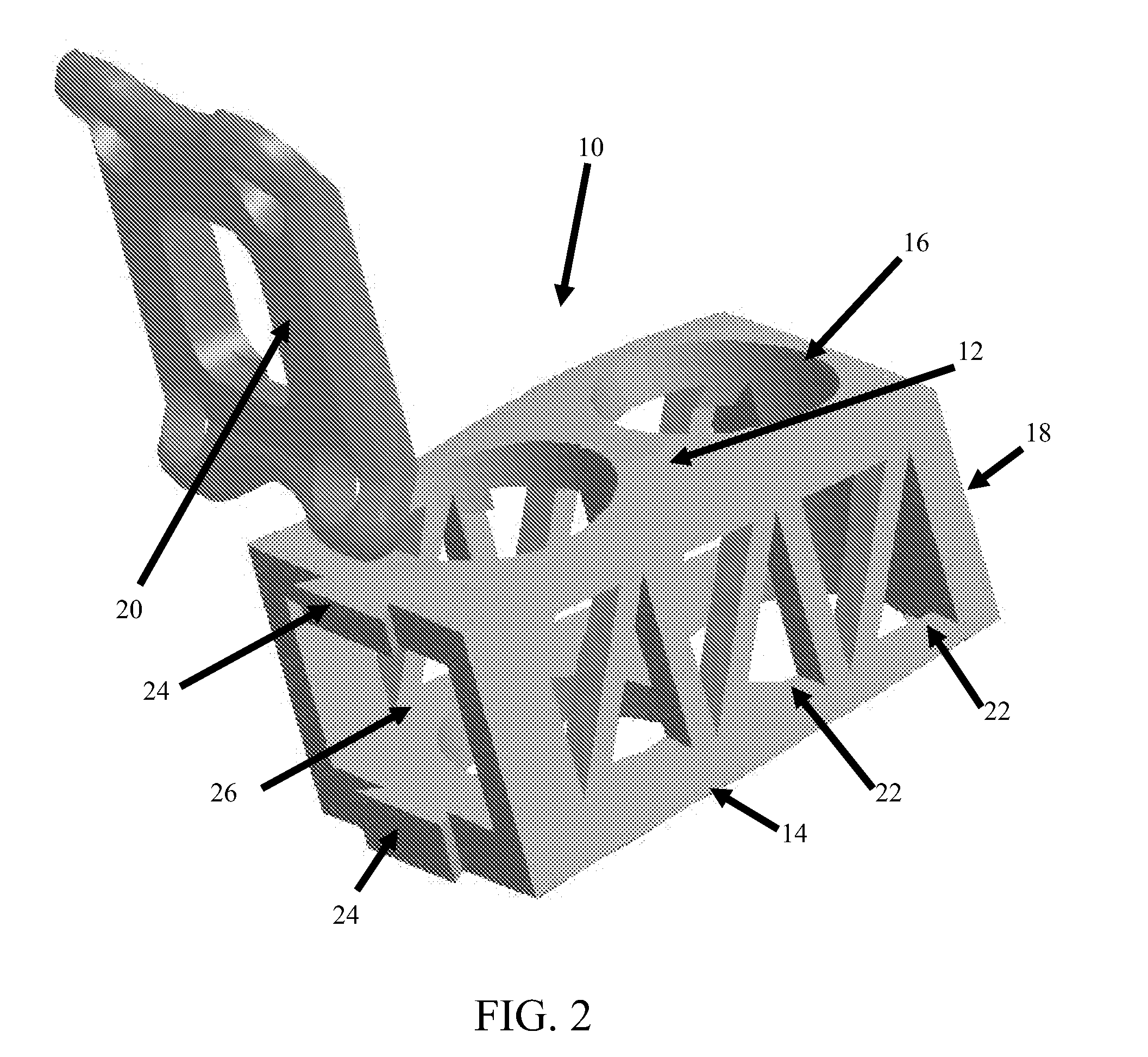
[0030]Several embodiments of a fixation and fusion cage with interlocking plate constructed in accordance with the teachings of the present invention are shown in the figures, wherein like numerals indicate like parts. Turning now to FIG. 1, a fixation and fusion cage constructed in accordance with the teachings of the present invention is indicated generally by the numeral 10. Fixation and fusion cage 10 of the present invention is preferably generally rectangular in shape and includes an upper cage surface 12 and a lower cage surface 14 (hereinafter referred to as upper cage surface and lower cage surface). Each of the upper and lower cage surfaces is sized and shaped to form a contoured surface that agrees with the anatomy of the contacting vertebral surfaces between which the present cage will be used. Each of upper and lower cage surfaces 12 and 14 also preferably has a plurality of openings 16 formed therein. Upper cage surface 12 and lower cage surface 14 are supported by sid...


PUM


Abstract

The present invention provides a fixation and fusion cage with interlocking plate comprising a central cage portion and interlocking plate that rigidly attaches to the front of the cage. The cage can be varied in shape to account for various clinical necessities such as lordosis. The invention may be installed in an offset configuration so as to avoid damage to blood vessels. The device may be constructed from radiolucent material to allow for visualization of bone fusion within the cage.

Description

BACKGROUND OF THE INVENTION[0001]The present invention relates generally to an implantable device for promoting the fixation and fusion of adjacent bony structures, and a method of using the same. More specifically, the present invention relates to an anterior fixation and fusion cage with an optional integrated plate that may be inserted into an intervertebral space, and a method of using the same.[0002]Fusion cages provide a space for inserting bone graft between adjacent portions of bone. These cages are used to increase disc height and provide stability to damaged or degenerative spines. Such cages are made from a variety of materials. These materials include but are not limited to titanium, carbon fiber, and polyetheretherketone (PEEK). Fusion cages are often hollow and can be porous to allow for maximum bone growth through the cage and into adjacent vertebral bodies. Cages of the nature described here are used to treat numerous spinal disorders including but not limited to deg...

Claims


Application Information

Patent Timeline
IPC IPC(8): A61F2/44A61B17/58A61B17/04
CPCA61B17/7059A61B17/8057A61F2/447A61F2002/2817A61F2002/2835A61F2002/30387A61F2002/30578A61F2002/30604A61F2002/30616A61F2002/30785A61F2002/30904A61F2220/0025A61F2310/00017A61F2310/00023A61F2310/00029A61F2002/30593
Inventor ABERNATHIE, DENNIS LEE
Owner ABERNATHIE DENNIS LEE
Why Eureka
Try Eureka