
Robots with Occlusion Avoidance Functionality

a technology of occlusion avoidance and robots, applied in the field of robots, can solve the problems of increasing the working range of robots, increasing computation time, and difficult application of interactive motion methods

Active Publication Date: 2008-12-18
HONDA RES INST EUROPE
View PDF19 Cites 53 Cited by
  • Summary
  • Abstract
  • Description
  • Claims
  • Application Information

AI Technical Summary

Benefits of technology

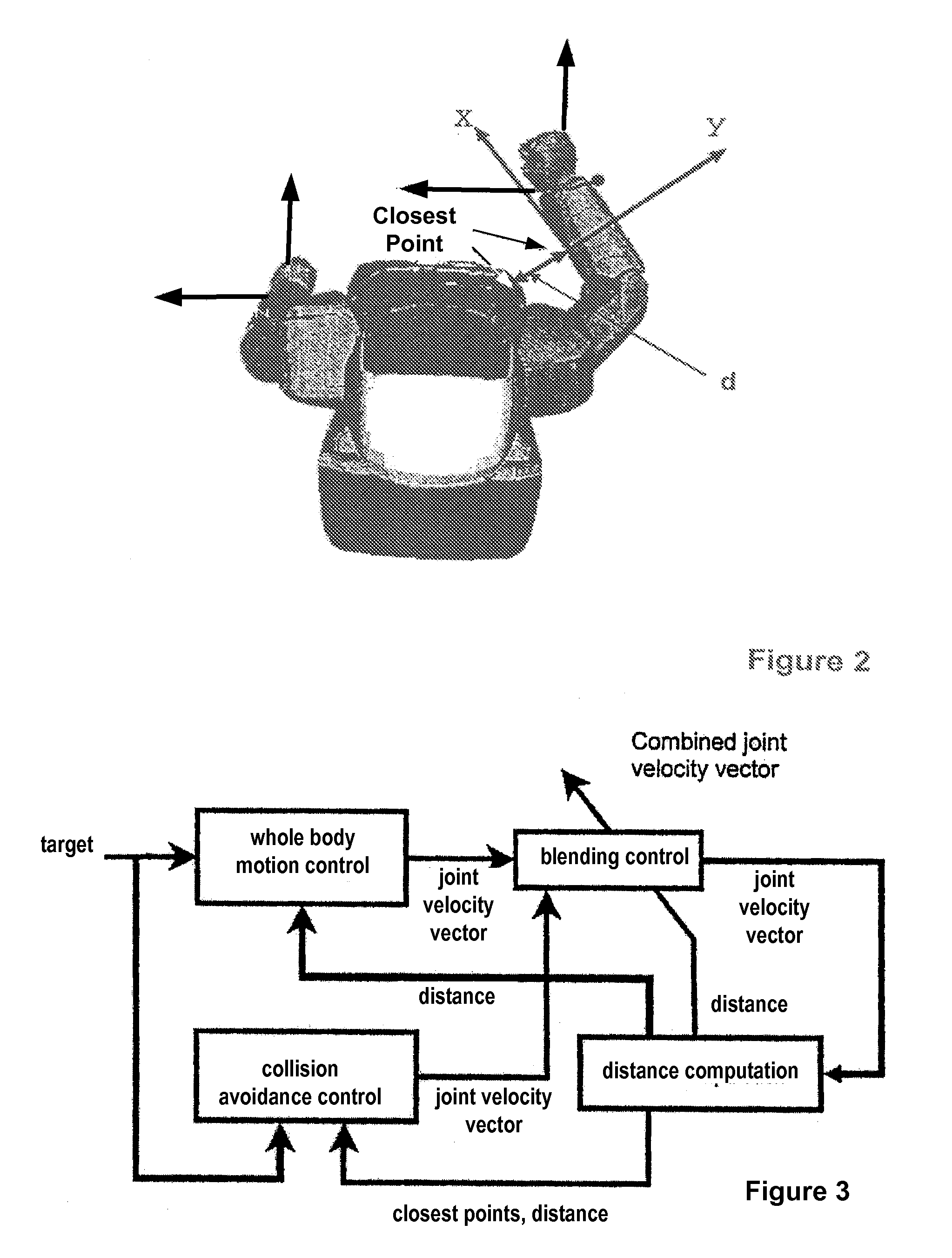
[0018]One embodiment of the present invention relates to controlling a robot having at least one visual sensor. The target of a motion of the robot is defined. A motion control signal adapted for the robot reaching the target is then calculated. A collision avoidance control signal based on the closest points of segments of the robot and a virtual object between the visual sensor and the target are calculated. The motion control signal and the collision avoidance control signal are combined. The weight of the motion control output signal is higher when a calculated collision risk is lower. A motion of the robot is controlled according to the combined signal such that no segment of the robot enters the space defined by the virtual object.
[0021]In one embodiment of the present invention, the weights can be changed gradually in order to perform a soft task switching between target reaching by motion and collision avoidance.
[0030]In one embodiment of the present invention, the technique is implemented on a humanoid robot such as a bipedal walking robot. The arm may avoid occlusion of the visual sensor of the robot.

Problems solved by technology

The collision avoidance does not necessarily stop the robot's target reaching motions and may expand the robot's working range.
However, these methods are difficult to apply to interactive motions because the computation time becomes longer as the degrees of freedom of robots (e.g., humanoid robots) increase.

Method used


Image

  • Robots with Occlusion Avoidance Functionality
  • Robots with Occlusion Avoidance Functionality
  • Robots with Occlusion Avoidance Functionality

Examples


example

[0078]In order to avoid occlusion problems, a “virtual object” in space is defined and taken into account when performing the collision avoidance. Thus, space can be defined where a robot segment is not allowed to penetrate. This means that an area can be defined where a robot segment is not allowed to enter. Such area may be used as an “occlusion avoidance.” One of the major problems when robots grasp something is occlusions that are caused by their hands hiding target objects. In one embodiment of the present invention, a virtual obstacle can be configured and placed between the robot head and the target so that the hands of the robot do not interfere with the robot's view of the target. The virtual object may be inactivated right before the robot reaches to the object.

[0079]Embodiments of the present invention relate to a technique for a safety mechanism that protects articulated robots and the environment in which the robot is operating. In particular, embodiments may be employe...


PUM


Abstract

A method for controlling a robot having at least one visual sensor. A target for a motion of the robot is defined. A motion control signal adapted for the robot reaching the target is calculated. A collision avoidance control signal based on the closest points of segments of the robot and a virtual object between the visual sensing means and the target is calculated. The motion control signal and the collision avoidance control signal are weighted and combined. The weight of the motion control signal is higher when a calculated collision risk is lower. The motion of the robot is controlled according to the combined signal so that no segment of the robot enters the space defined by the virtual object.

Description

RELATED APPLICATIONS[0001]This application claims priority under 35 U.S.C. § 119(a) to European Patent Application number 07 104 820, filed on Mar. 23, 2007, which is incorporated by reference herein in its entirety. This application is related to U.S. patent application Ser. No. 12 / 052,483, filed on Mar. 20, 2008 (Attorney Dkt No.: 23077-13969); and U.S. patent application Ser. No. 12 / 050,948, filed on Mar. 19, 2008 (Attorney Dkt No.: 23077-13970), which are incorporated by reference herein in their entirety.FIELD OF THE INVENTION[0002]The present invention generally relates to robots, and specifically to robots acting autonomously.BACKGROUND OF THE INVENTION[0003]When controlling a trajectory of an effector such as a robot, a target state needs to be defined. The target state is, for example, defined as an object that is to be handled by a manipulating arm of a robot. In general, the position of the object can be described by three parameters. In addition to the object position, i...

Claims


Application Information

Patent Timeline
Patent Type & Authority Applications(United States)
IPC IPC(8): G06F17/00
CPCB25J9/1666
Inventor SUGIURA, HISASHI
Owner HONDA RES INST EUROPE
Learn More