Anode Bleed Control Strategy for Improved Water Management and Hydrogen Utilization

a fuel cell and control strategy technology, applied in electrochemical generators, instruments, liquid/fluent solid measurements, etc., can solve the problems of higher voltage degradation rate, fuel cell stack instability, carbon corrosion, etc., and achieve the effect of improving water management and addressing durability and performance concerns

a fuel cell and control strategy technology, applied in electrochemical generators, instruments, liquid/fluent solid measurements, etc., can solve the problems of higher voltage degradation rate, fuel cell stack instability, carbon corrosion, etc., and achieve the effect of improving water management and addressing durability and performance concerns

US20080312849A1Active Publication Date: 2008-12-18GM GLOBAL TECH OPERATIONS LLC

Image

  • Anode Bleed Control Strategy for Improved Water Management and Hydrogen Utilization
  • Anode Bleed Control Strategy for Improved Water Management and Hydrogen Utilization
  • Anode Bleed Control Strategy for Improved Water Management and Hydrogen Utilization

Examples


Embodiment Construction

[0015]The following discussion of the embodiments of the invention directed to a control strategy for ending an anode bleed in an anode flow-shifting fuel cell architecture is merely exemplary in nature, and is in no way intended to limit the invention or its applications or uses.

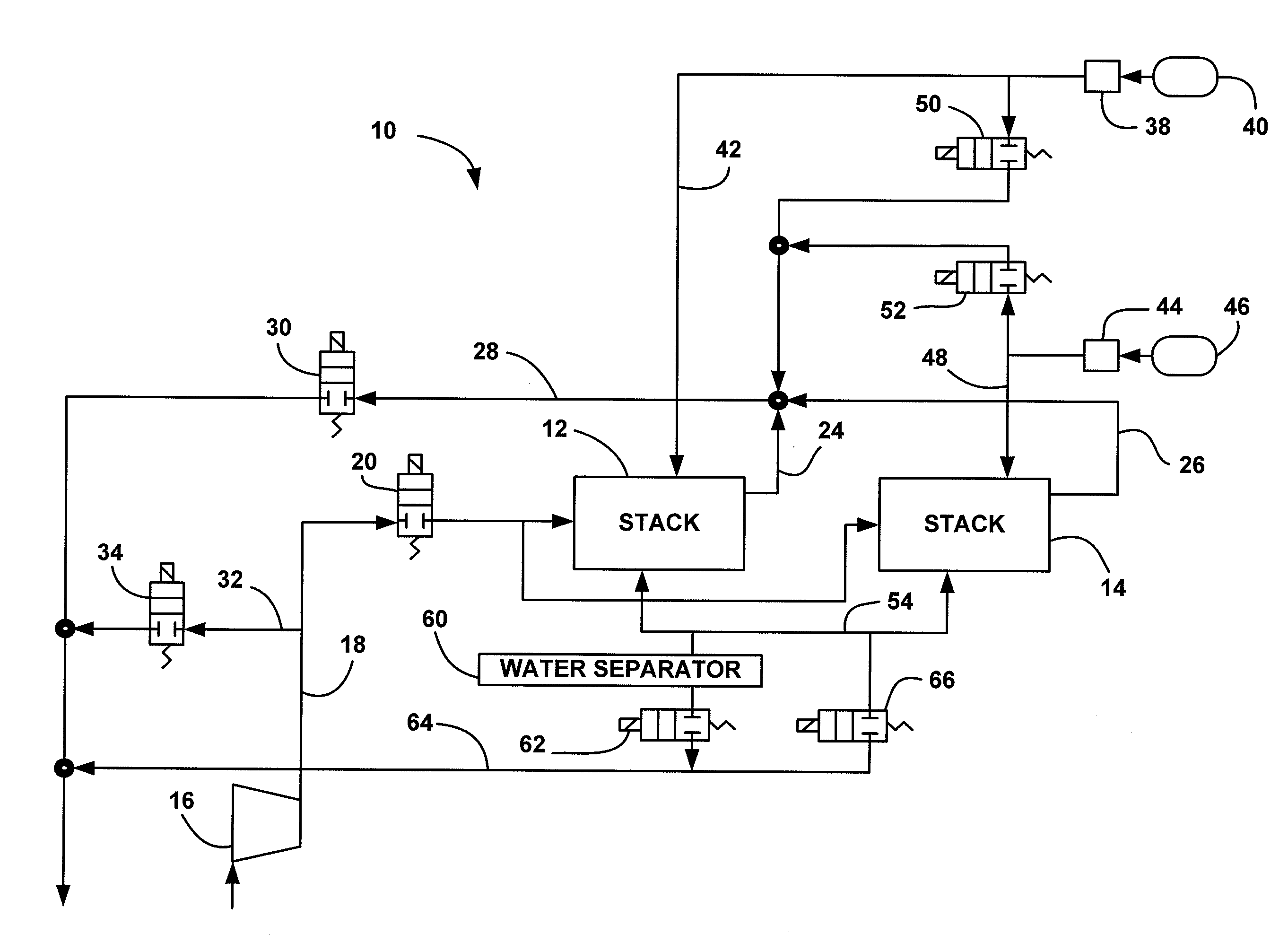
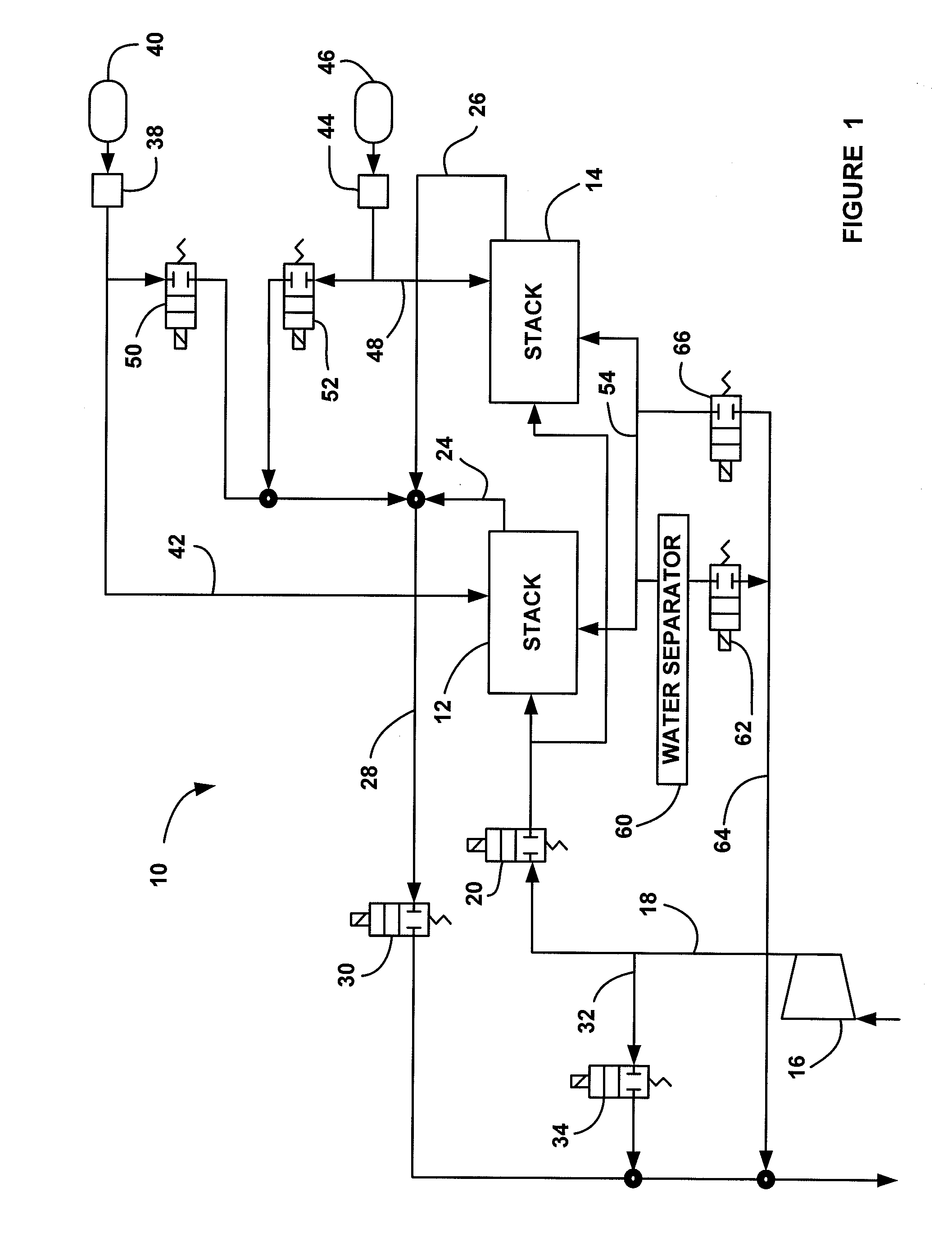
[0016]FIG. 1 is a schematic block diagram of a fuel cell system 10 including a first split fuel cell stack 12 and a second split fuel cell stack 14. A compressor 16 provides cathode input air on cathode input line 18 to the split stacks 12 and 14 through a normally closed cathode input valve 20. Cathode exhaust gas is output from the split stack 12 on line 24 and cathode exhaust gas is output from the split stack 14 on line 26 where the cathode exhaust gas is combined into a single cathode output line 28. A normally closed cathode back pressure valve 30 controls the flow of the cathode exhaust gas through the line 28. A cathode by-pass line 32 between the input line 18 and the output line 28 allows the cath...


PUM


Abstract

A control strategy for bleeding an anode side of fuel cell stack in a fuel cell system that improves water management and addresses durability and performance concerns. The method includes determining when to begin the anode bleed, typically by estimating or measuring the amount of nitrogen in the anode side of the stack. The method also includes determining when to end the anode bleed based on the volume of gas that has been bled. The method determines the mole flow rate of the anode gas flowing through a bleed valve, integrates the mole flow rate to get the number of moles of the gas that have passed through the bleed valve, determines a desired amount of moles to be bled, and ends the bleed when the actual number of moles of the gas equals the desired number of moles of the gas.

Description

BACKGROUND OF THE INVENTION[0001]1. Field of the Invention[0002]This invention relates generally to a control strategy for controlling an anode bleed from a fuel cell stack and, more particularly, to a control strategy for controlling an anode bleed from split fuel cell stacks that is based on the amount of anode gas that is bled so as to improve water management and address durability and performance issues.[0003]2. Discussion of the Related Art[0004]Hydrogen is a very attractive fuel because it is clean and can be used to efficiently produce electricity in a fuel cell. A hydrogen fuel cell is an electro-chemical device that includes an anode and a cathode with an electrolyte therebetween. The anode receives hydrogen gas and the cathode receives oxygen or air. The hydrogen gas is dissociated in the anode to generate free protons and electrons. The protons pass through the electrolyte to the cathode. The protons react with the oxygen and the electrons in the cathode to generate wate...

Claims


Application Information

Patent Timeline
18 Dec 2008
Publication
US20080312849A1
IPC
G01F1/34
CPC
H01M8/04231; H01M8/04462; Y02E60/50; H01M8/04992; H01M8/04761
Inventors
GADE, PRASAD; SINHA, MANISH