
I/O device switching method

a technology of switching method and server device, which is applied in the direction of error detection/correction, instruments, computing, etc., can solve the problems of complex operation management, failure of server device, and complicated reliability measures, so as to achieve accurate failure recovery and enhance the reliability of server device including i/o switch

Inactive Publication Date: 2008-12-18
HITACHI LTD
View PDF8 Cites 33 Cited by
  • Summary
  • Abstract
  • Description
  • Claims
  • Application Information

AI Technical Summary

Benefits of technology

[0008]An object of the present invention is to enhance the reliability of a server device including having an I / O switch.
[0012]According to the present invention, reliability in a server device including an I / O switch can be enhanced. Particularly, when a failure occurs in a certain I / O device, a management table is consulted to select a standby I / O device, and connection switching for the I / O devices is controlled so as to connect an I / O switch to which a computer is connected, to the I / O device, whereby failure recovery can be accurately performed.

Problems solved by technology

However, if the correspondence between the server devices and the I / O devices is fixed, when the usage and the like of the server devices are changed, the I / O devices must be mounted or dismounted, making operation management complicated.
According to the related art, although the allocation of I / O devices to a server device is made flexible by the I / O switch, measures for reliability become complicated.
However, when a failure occurs in an I / O device connected to the I / O switch, since processing of the server device is halted due to the failure in the I / O device, it appears that a failure occurs in the server device.
Therefore, even if only the server device is switched using a conventional method, if the failure in the I / O device is not eliminated, recovery from the failure is impossible.
This means that a server device including an I / O switch cannot be recovered simply by detecting a failure in the server device differently from a conventional method.

Method used


Image

  • I/O device switching method
  • I/O device switching method
  • I/O device switching method

Examples


Embodiment Construction

[0037]Hereinafter, embodiments of the present invention will be described with reference to the drawings.

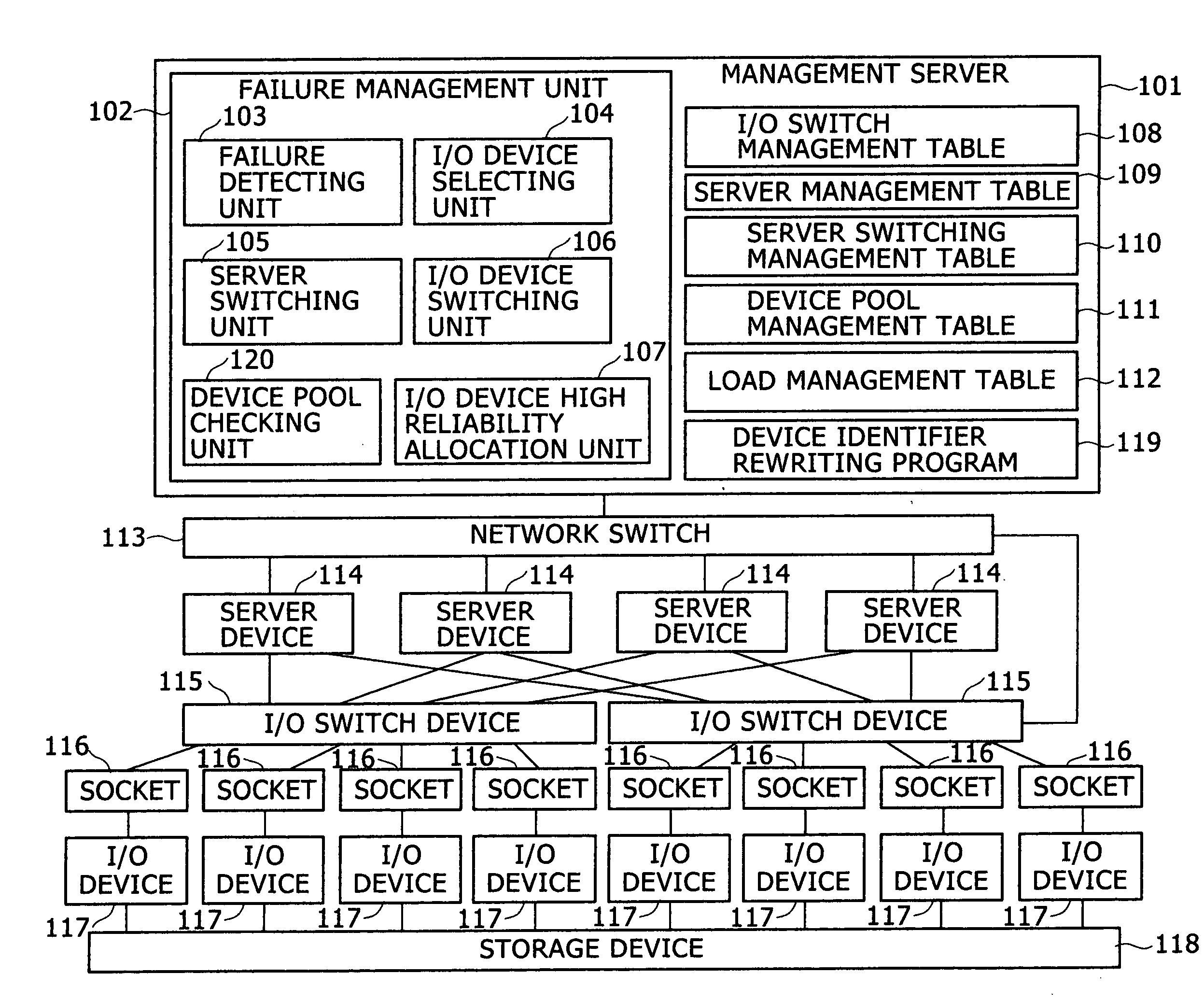
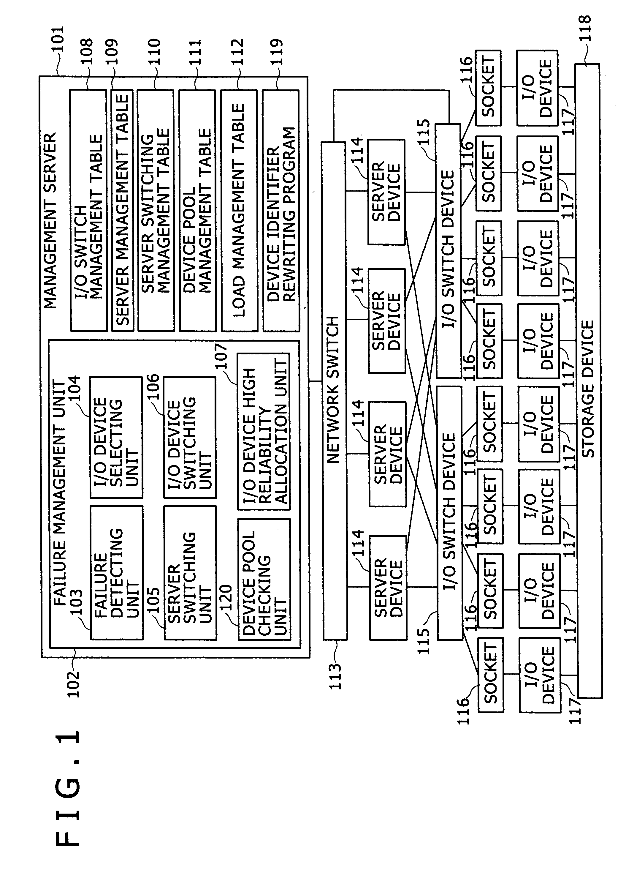
[0038]FIG. 1 is a drawing showing an overall configuration of a computer system of one embodiment.

[0039]In the computer system, a management server 101 is connected to plural servers 114 via a network switch 113, and further plural server devices 114 are connected to plural switch devices 115. IO devices 117 are connected to the switch devices 115 via plural sockets 116, and several of the IO devices are connected with a storage device 118 so that the server devices 114 can access the storage device 118. Usually, a job is executed between the server device 114 and the storage device 118, and the management server 101 performs failure monitoring and recovery control of the server devices 114 and the IO devices 117.

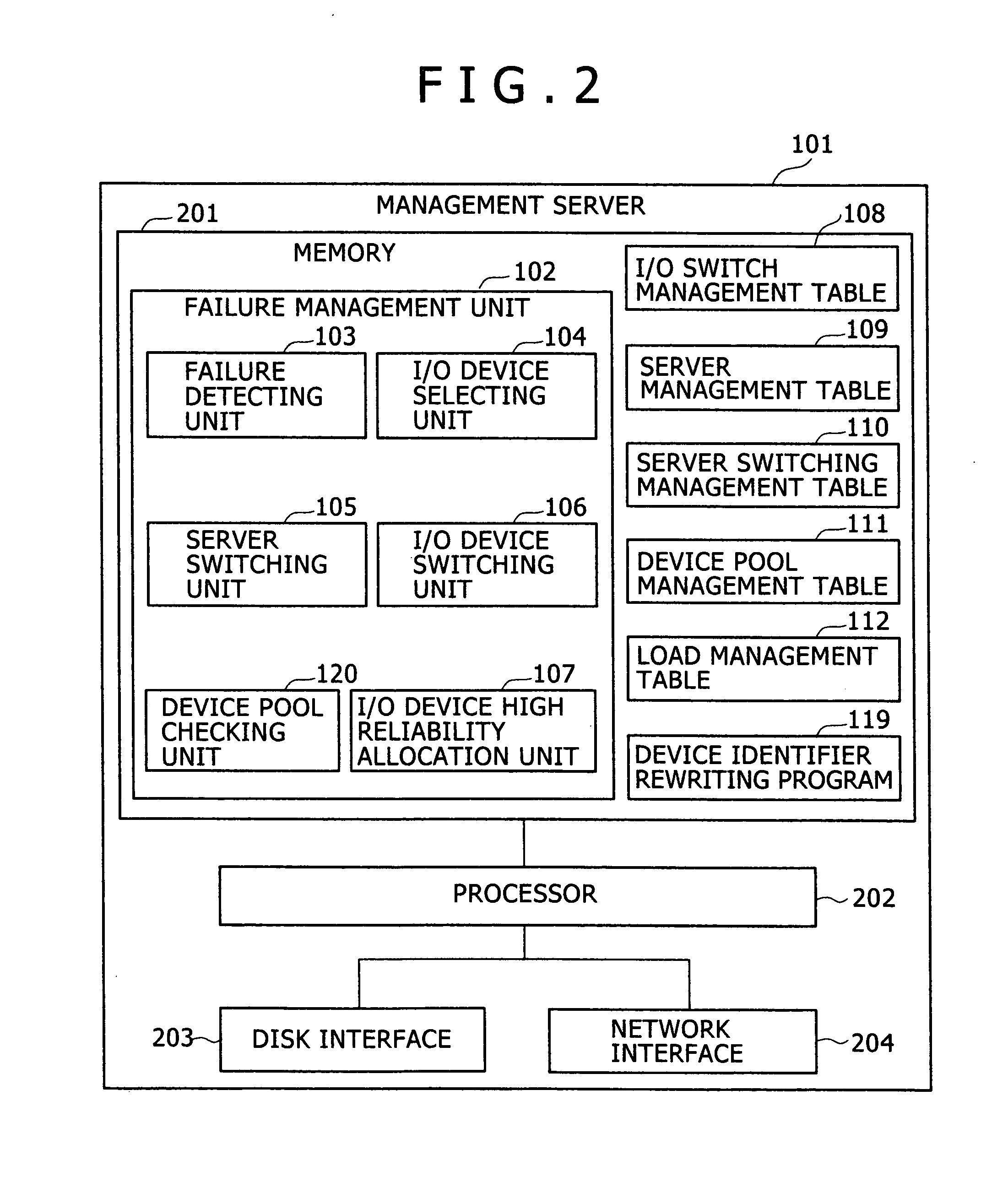
[0040]The management server 101 includes a failure management unit 102, various management tables 108 to 112, and a device identifier rewriting program 119. The failure ...


PUM


Abstract

An I / O device management table that manages the types of I / O devices connected to an I / O switch is provided, and one or plural unallocated I / O devices are defined and registered as standby I / O devices. When a failure occurs in any of I / O devices, the I / O device management table is used to select an I / O device of the same type as the failed I / O device from the standby I / O devices, and the selected I / O device is allocated to a computer to which the failed I / O device is connected. I / O device management can be eased at failure in a computer including an I / O switch device.

Description

CLAIM OF PRIORITY [0001]The present application claims priority from Japanese application JP 2007-156339 filed on Jun. 13, 2007, the content of which is hereby incorporated by reference into this application.BACKGROUND OF THE INVENTION[0002]The present invention relates to an I / O device switching method, and more particularly to an I / O device switching method that enables selective switching of plural I / O devices connected to a server device having an I / O switch, and a computer system that includes a management server that performs the switching control.[0003]There are cases where a server device is connected with plural types of external devices such as network devices and storage devices that respectively have different protocols. Therefore, the server device is provided with plural I / O devices that process different protocols and make connections between the server device and external devices. In the case of general server devices, the correspondence between the server devices an...

Claims


Application Information

Patent Timeline
IPC IPC(8): G06F3/00
CPCG06F11/2007G06F11/2017G06F11/2033G06F11/2038G06F11/2092
Inventor TAKAMOTO, YOSHIFUMI
Owner HITACHI LTD
Learn More