Punch press tool for stamping successive multicharacter impressions into a workpiece

a multi-character impression and punch press technology, applied in stamping, printing, mechanical working/deformation, etc., can solve the problems of not being able to operate the punch press using a high-speed computer controlled punch press, not being able to develop a punch press tool for stamping successive multi-character impressions into workpieces, and not being able to make impressions in metal

Active Publication Date: 2008-12-25
MATE PRECISION TOOLING
View PDF14 Cites 38 Cited by
  • Summary
  • Abstract
  • Description
  • Claims
  • Application Information

AI Technical Summary

Benefits of technology

[0006]These and other more detailed and specific objects and advantages of the present invention will be better understood by reference to the following figures and detailed description which illustrate by way of example but a few of the various forms of the invention within the scope of the appended claims.
[0007]Briefly, the present invention provides a punch press tool for stamping successive multicharacter impressions in a workpiece such as a piece of steel, sheet metal, or other workpiece, that includes a guide body in which a stamp driver that is slidably mounted for being driven downwardly toward the workpiece by a punch press ram which is a standard part of a high speed commercial computer operated punch press. A multicharacter marking stamp is supported at the lower en

Problems solved by technology

Thus, the patented device is not suitable for making an impression in metal nor for being operated by the reciprocating ram of a punch press.
While numbering devices themselves are available commercially, there is no way to operate them using a high speed computer controlled punch press.
Consequently, as far as the applicants were abl

Method used


Image

  • Punch press tool for stamping successive multicharacter impressions into a workpiece
  • Punch press tool for stamping successive multicharacter impressions into a workpiece
  • Punch press tool for stamping successive multicharacter impressions into a workpiece

Examples


Embodiment Construction

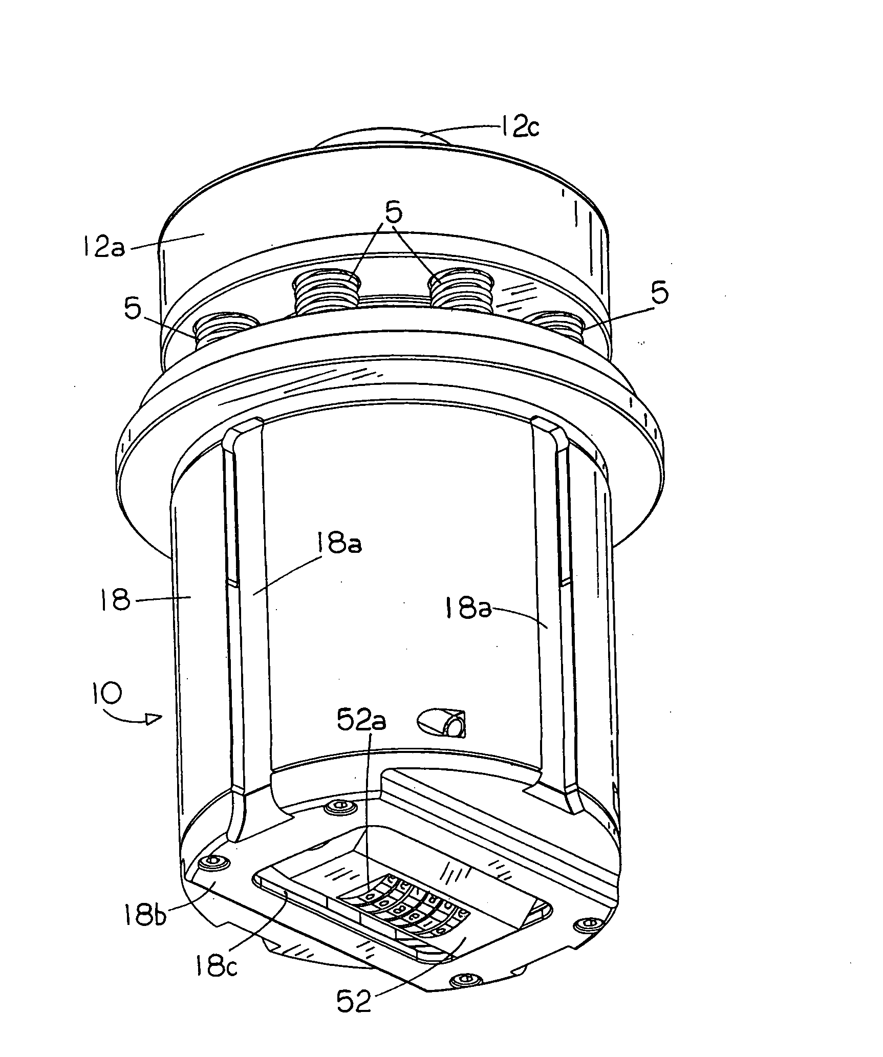
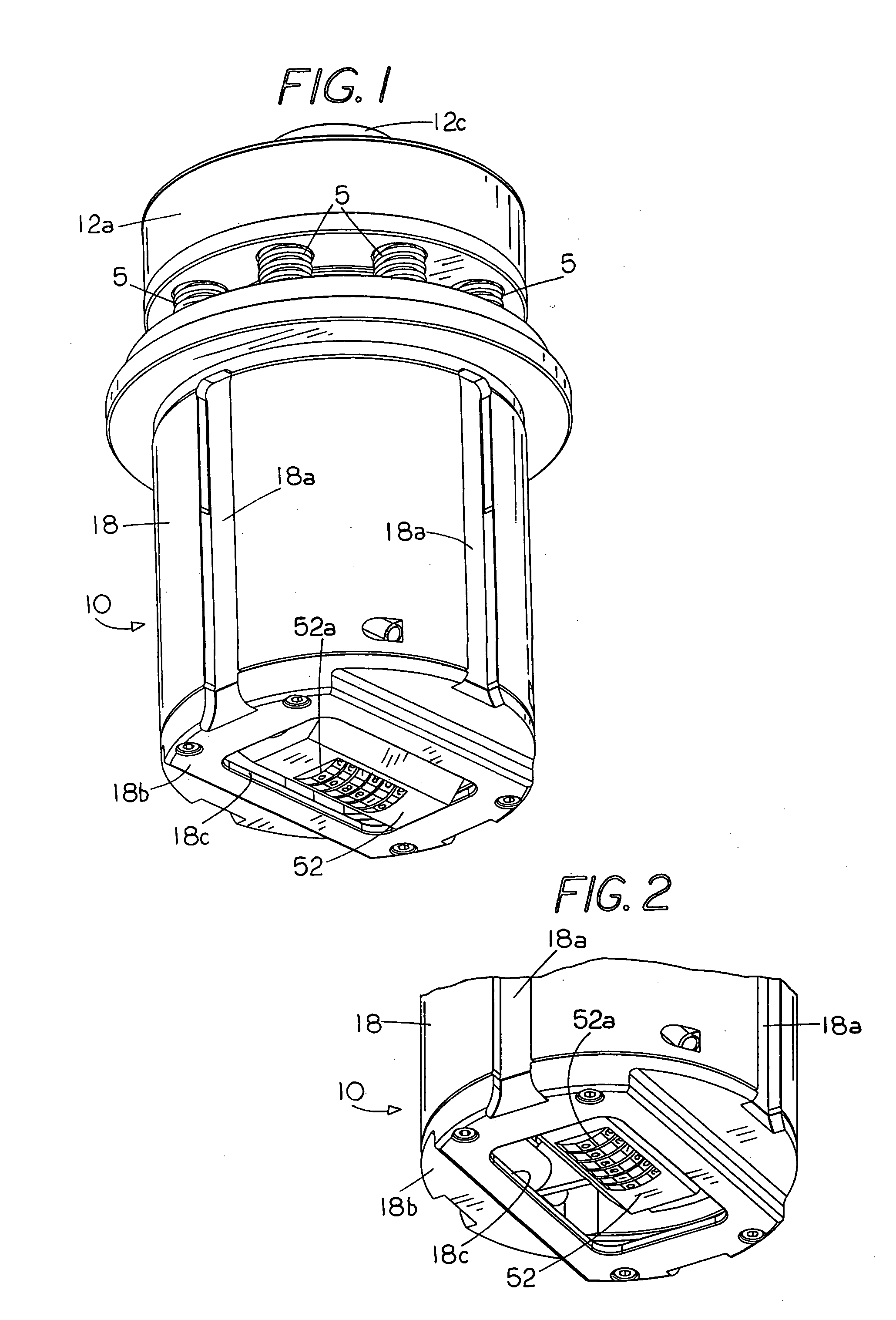
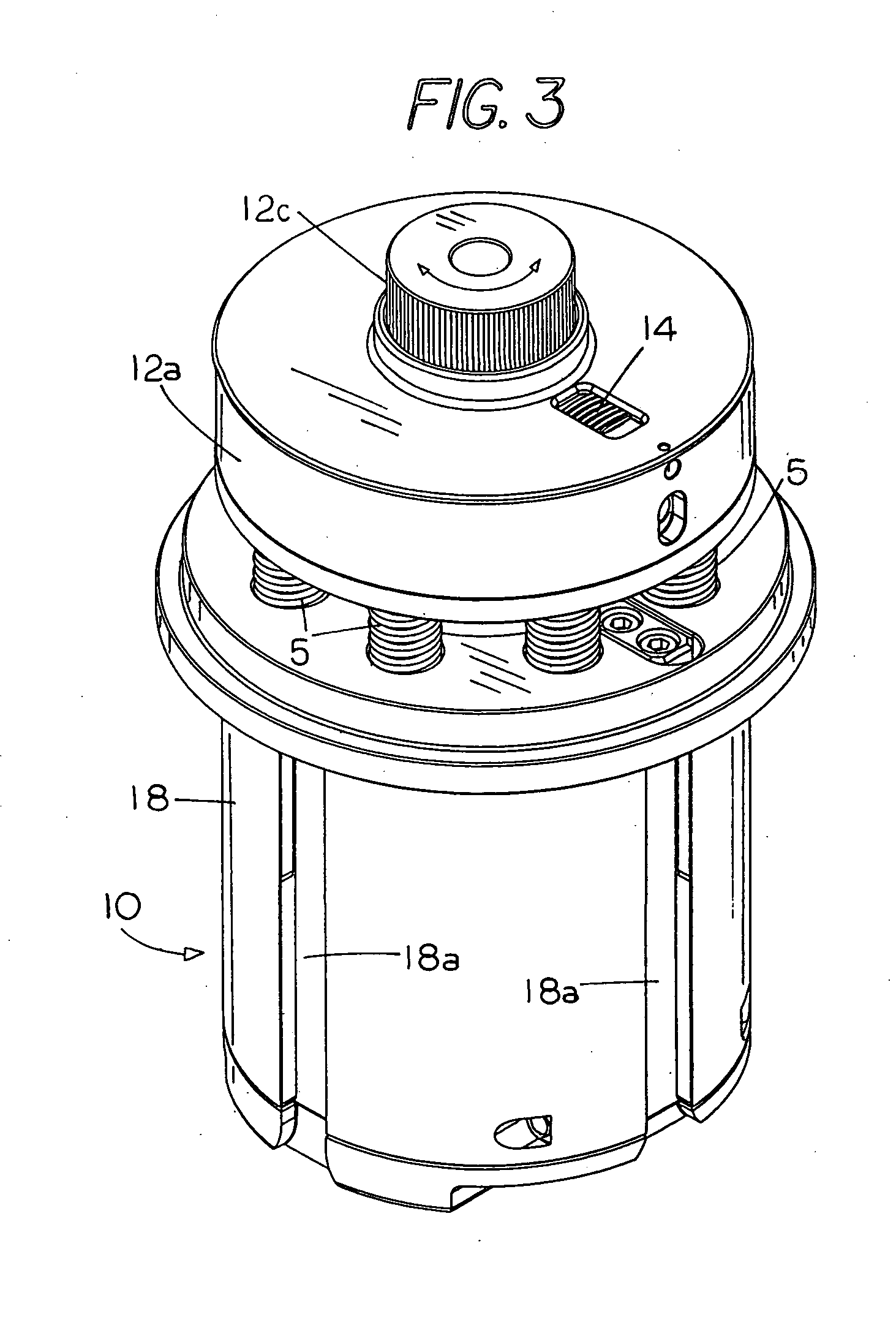
[0018]In FIGS. 1-3 the punch press tool according to the invention, indicated generally by the numeral 10 comprises two major parts; a guide body 18 and a stamp driver 12 of cylindrical shape having a cylindrical boss 12a at its upper end that is bored at 12b to receive an adjustable striker head 12c of cylindrical shape which is screw threaded into the lower portion of the stamp driver by means of threads 12d. The lower part of the stamp driver 12 is slidably mounted in a vertically disposed bore 16 in the guide body 18 which is provided on its outer surface with circumferentially spaced apart longitudinally extending keyways 18a for holding it at the proper angle about a vertical axis.

[0019]FIGS. 4 and 5 show how during use, the stamping tool 10 is mounted for operation on the upper turret 20 of a punch press by being placed within a circular tool holder 22 of conventional well known construction that is itself supported within an adapter ring 24. The tool 10 is supported on the t...


PUM

PropertyMeasurementUnit
Thicknessaaaaaaaaaa
Forceaaaaaaaaaa
Lengthaaaaaaaaaa

Abstract

A punch press tool for stamping successive multicharacter impressions into a workpiece such as a piece of steel, sheet metal, or other workpiece, includes a guide body in which a stamp driver is slidably mounted for being driven downwardly toward the workpiece by a punch press ram which is a standard part of a high speed commercial punch press. A multicharacter marking stamp is supported at the lower end of the stamp driver for reciprocal movement therewith. The marking stamp includes multicharacter wheels that are rotated automatically during operation for advancing characters in sequence responsive to the movement of a character advancing arm. At least one character stamp operating lever is operatively associated with the punch press tool for articulation responsive to motion imparted to the tool by the ram. The lever has an operating element that is operatively associated with the character advancing arm of the multicharacter stamp for indexing the arm to enable successive characters thereof to be placed in an operating position responsive to a stroke of the punch press ram.

Description

FIELD OF THE INVENTION[0001]This invention relates to the punch and die art and more particularly to a punch press stamping tool for marking a workpiece with a stamped impression of numbers or letters in its surface.BACKGROUND OF THE INVENTION[0002]In the punch and die art and particularly in the field of high-speed automated forming and punching equipment for punching and forming sheet material, e.g., sheet metal and especially in the case of automated turret punch presses, the punch presses are operated by computer to rapidly perform a series of punching or forming operations. These punch presses which by themselves form no part of the present invention are typically provided with an upper turret and a lower turret that rotate and are indexed intermittently between punching operations. The turrets may, for example, hold as many as a dozen or more separate punches such as hole punches that are used one after another for performing given operations. When a punch is struck from above...

Claims


Application Information

Patent Timeline
IPC IPC(8): B26F1/14
CPCB44B5/0057B44B5/026B21D28/12Y10T83/9423
Inventor FERRY, GREGORY S.BERRY, DAVID A.
Owner MATE PRECISION TOOLING
Why Eureka
Try Eureka