Directional Drilling System and Software Method

a drilling system and software technology, applied in the field of directional drilling, can solve the problems of driller not being able to guarantee for sure in which direction, the sub is nontheless effectively fixed during drilling, and the orientation of the tool face will typically change,

Inactive Publication Date: 2008-12-25
MCCLARD KEVIN
View PDF29 Cites 94 Cited by
  • Summary
  • Abstract
  • Description
  • Claims
  • Application Information

AI Technical Summary

Benefits of technology

[0040]Accordingly, the present invention may comprise directional drilling expert software that may be utilized to drill a plurality of wells and to eliminate the need to have directional drillers on site at each well, and whereupon a single directional driller, or small group of directional drillers, or other human overseers might monitor the directional driller expert software as it handles hundreds of wells.

Problems solved by technology

In some cases, the angle of bend of the bent sub may be adjustable during operation by signaling downhole, but the bent sub is nontheless effectively usually fixed during drilling.
However, once drilling begins, the tool face orientation will typically change due to drill bit torque, weight on the bit, drilling fluid flow rate, the formation, and related forces that may twist the drill string.
Thus, the directional driller cannot guarantee for sure in what direction the well is actually being drilled at any given moment.
However, even with an MWD tool, the drilling may not proceed in the direction of the tool face due to various factors which might include changing formations, bit wear, washouts, hard spots, bit vibration patterns, slip-stick (repeated sticking and slipping of the bit), and the like.
Again, due to the offset between the drill bit and the magnetic sensor, the directional driller will not know for sure in what direction the bit is actually drilling.
Interpolation of drilling direction from the readings made further up the hole can be inaccurate.
The job is especially problematic when beginning a kick-off, which requires drilling in the desired direction, normally from a vertical position.
Although the directional driller has carefully selected the drilling device and made initial planning, it is not known how a given formation will respond to the drilling regime they have in mind.
It may be the amount of curvature they can build and / or the amount of weight which can be applied to the bit is limited.
Also, when the directional driller is not orienting and is rotary drilling, then the speed of rotation can affect the amount of directional change.
Directional drillers must often stay awake for long periods of time and therefore the decisions of the directional drillers are particularly subject to human errors.
Directional drilling services are not standardized.
The above available tools do not insure results.
Much more costly than directional drillers are downhole directional drilling systems that utilize varible pads, rotary steerable drives as described briefly above, compass sections very close to the drill bit, and the like, in a downhole closed-loop directional drilling system.
However, these downhole closed-loop drilling systems are very expensive.
They are subject to drilling errors as discussed even with the high costs thereof.
Moreover, the failure of a device therein requires a relatively lengthy time for replacement because the entire drill string must be removed from the wellbore and then reinserted.
The above cited art does not provide directional drilling expert software for controlling a plurality of drilling operations simultaneously that may be utilized with surface equipment and less expensive bottom hole assemblies to reduce directional drilling costs and improve directional drilling accuracy.

Method used


Image

  • Directional Drilling System and Software Method
  • Directional Drilling System and Software Method
  • Directional Drilling System and Software Method

Examples


Embodiment Construction

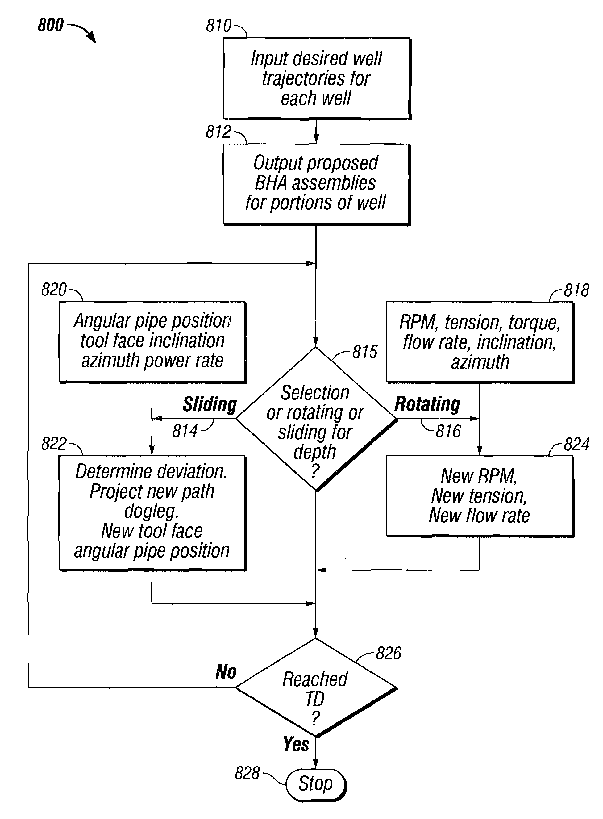
[0064]The present invention effectively provides a directional driller expert software system which, when given the projected well path, will then perform the functions of a directional driller in planning the bottom hole assembly, controlling the rig motors, receiving magnetic survey information, making adjustments to the tool face, and the like, as discussed below. While in the prior art, a directional driller is necessary for each well, in accord with the present invention, a single directional driller or other human overseer may be used to oversee many, and perhaps hundreds of wells simultaneously, thereby saving considerable costs.

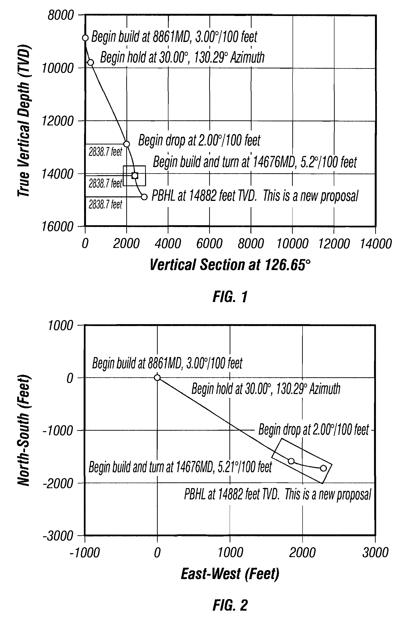
[0065]FIG. 1 shows a two-dimensional view of a sample projected well path trajectory 10 measured with respect to true vertical depth from a particular angle. FIG. 2 is a two-dimensional view of well path trajectory in feet with respect to North-South and East-West axes. A projected well path is normally provided to the directional driller. In the pres...


PUM


Abstract

A software method for directionally drilling a plurality of wells capable of providing directional drilling services to hundreds of wells. The software method may comprise steps from determining a BHA for a portion of a well, determining a deviation between the desired trajectory of the well bore and an actual trajectory of the well bore as measured at the nonmagnetic measurement portion of the bottom hole assembly, determining a dogleg of the actual trajectory, and determining a correction trajectory to reduce the deviation between the desired trajectory and the actual trajectory which produces a dogleg less than a predetermined value. The trajectory may be projected to the bit even though the nonmagnetic measurement portion of the bottom hole assembly is often separated therefrom by significant distances.

Description

BACKGROUND OF THE INVENTION[0001]1. Field of the Invention[0002]The present invention relates generally to directional drilling and, more particularly, to directional drilling expert software, that controls surface and / or subsurface components of a drilling system to direct the direction of drilling along a proposed well path.[0003]2. Description of the Background[0004]Directional drilling typically involves drilling non-vertical wells. A specialized type of driller, a directional driller, is often utilized to control the drilling rig for this purpose. Typically, the directional drillers are given a well path to follow that is predetermined by engineers and geologists before the drilling commences.[0005]Directional wells may be drilled for purposes such as: (1) increasing the exposed section length through the reservoir by drilling through the reservoir at an angle (2) drilling into the reservoir where vertical access is difficult or not possible such as within a city or under a lak...

Claims


Application Information

Patent Timeline
Patent Type & Authority Applications(United States)
IPC IPC(8): E21B7/00G06F19/00
CPCE21B7/04E21B44/00E21B47/022
Inventor MCCLARD, KEVIN
Owner MCCLARD KEVIN
Why Eureka
Try Eureka