Working Machine

a technology of working machine and working frame, which is applied in the direction of load-engaging elements, lifting devices, constructions, etc., can solve the problems of deteriorating assembly work efficiency, complicated assembly of working machine, and difficult assembly process to be performed efficiently, so as to improve assembly work efficiency. the effect of the assembly operation

Inactive Publication Date: 2008-12-25
NIHON KENKI CO LTD
View PDF33 Cites 8 Cited by
  • Summary
  • Abstract
  • Description
  • Claims
  • Application Information

AI Technical Summary

Benefits of technology

[0033]With this arrangement, when one of the plural number of operation levers is inclined, a signal consonant with the manipulation of the operation lever is output by corresponding signal output means, and the signal transmission means transmits this signal to the directional control valve to change the directional control valve. In this case, the plural number of operation levers, the signal...

Problems solved by technology

Therefore, an assembling of the working machine becomes complicated, and it is difficult for the assembly process to be performed efficiently.
This contributes very much to the deterioration of the assembly work efficiency.
Therefore, a plural number of hydraulic pipes, which connect a plural number of directional control valves to the individual hydraulic actuators, are intricately entangled around the valve unit, so that, a problem arises in that a great deal of time and labor are expended when connecting the hydraulic pipes.
A hydraulic pipe that connect...

Method used


Image

  • Working Machine
  • Working Machine
  • Working Machine

Examples


first embodiment

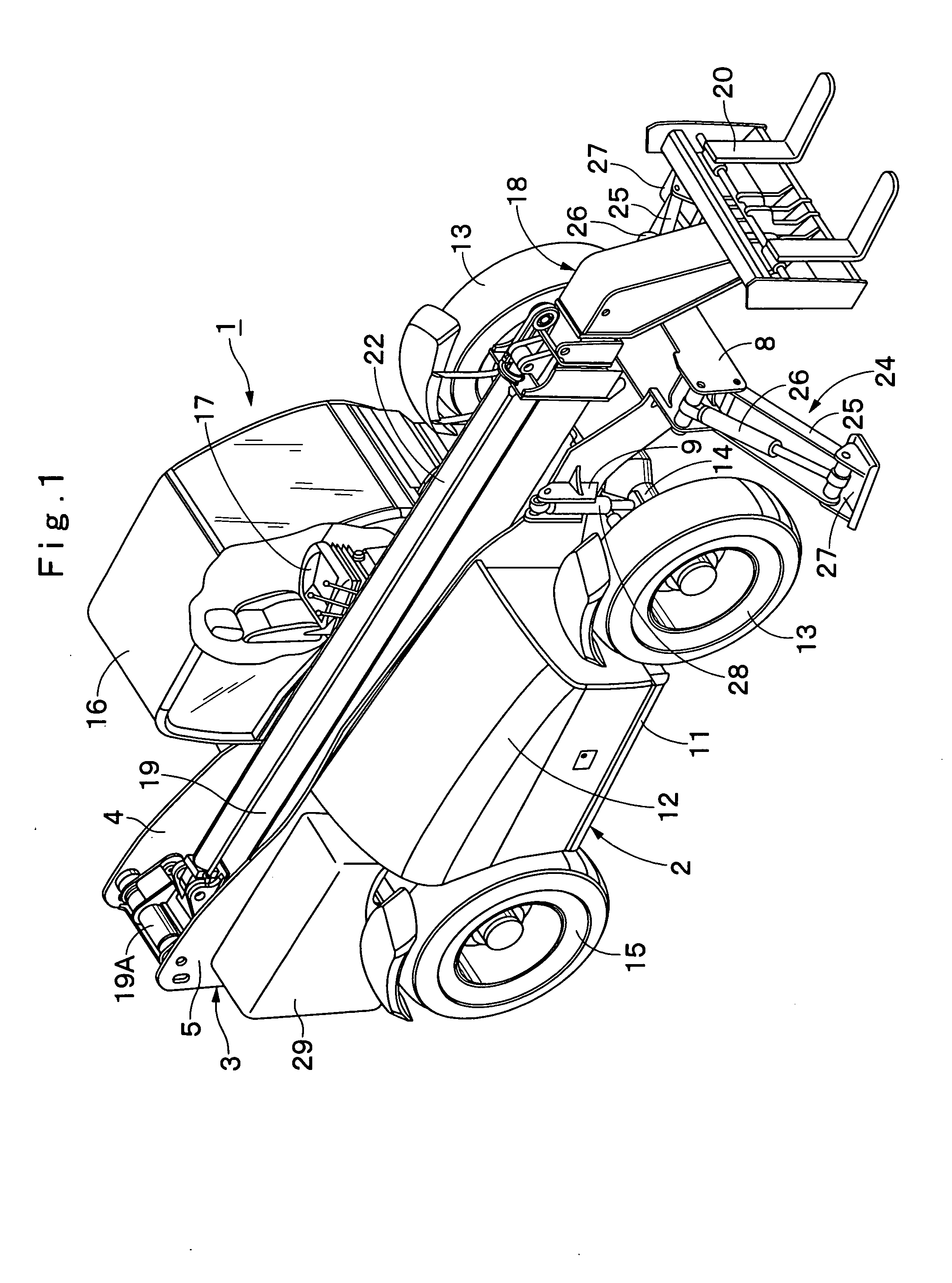
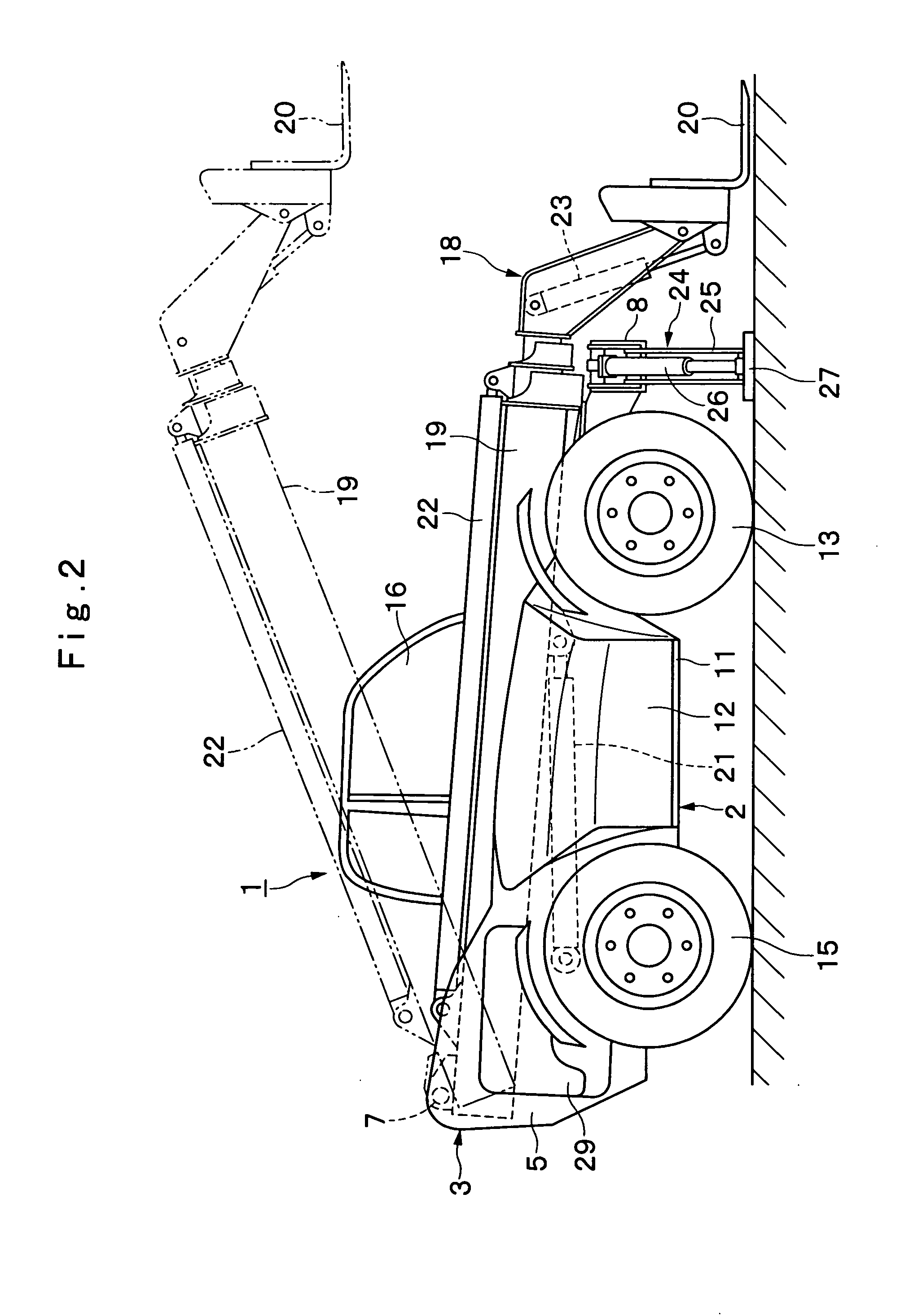
[0059]FIGS. 1 to 21 show the present invention. In the drawings, reference numeral 1 denotes a lift truck used as a working machine, and the lift truck 1 is roughly constituted by a vehicle body 2 of a mobile wheel type, and a boom apparatus 18 that will be described after. The lift truck 1 employs the boom apparatus 18 to deliver freight goods from ground level to an elevated position, for example, after arriving at a job site by self-propulsion.

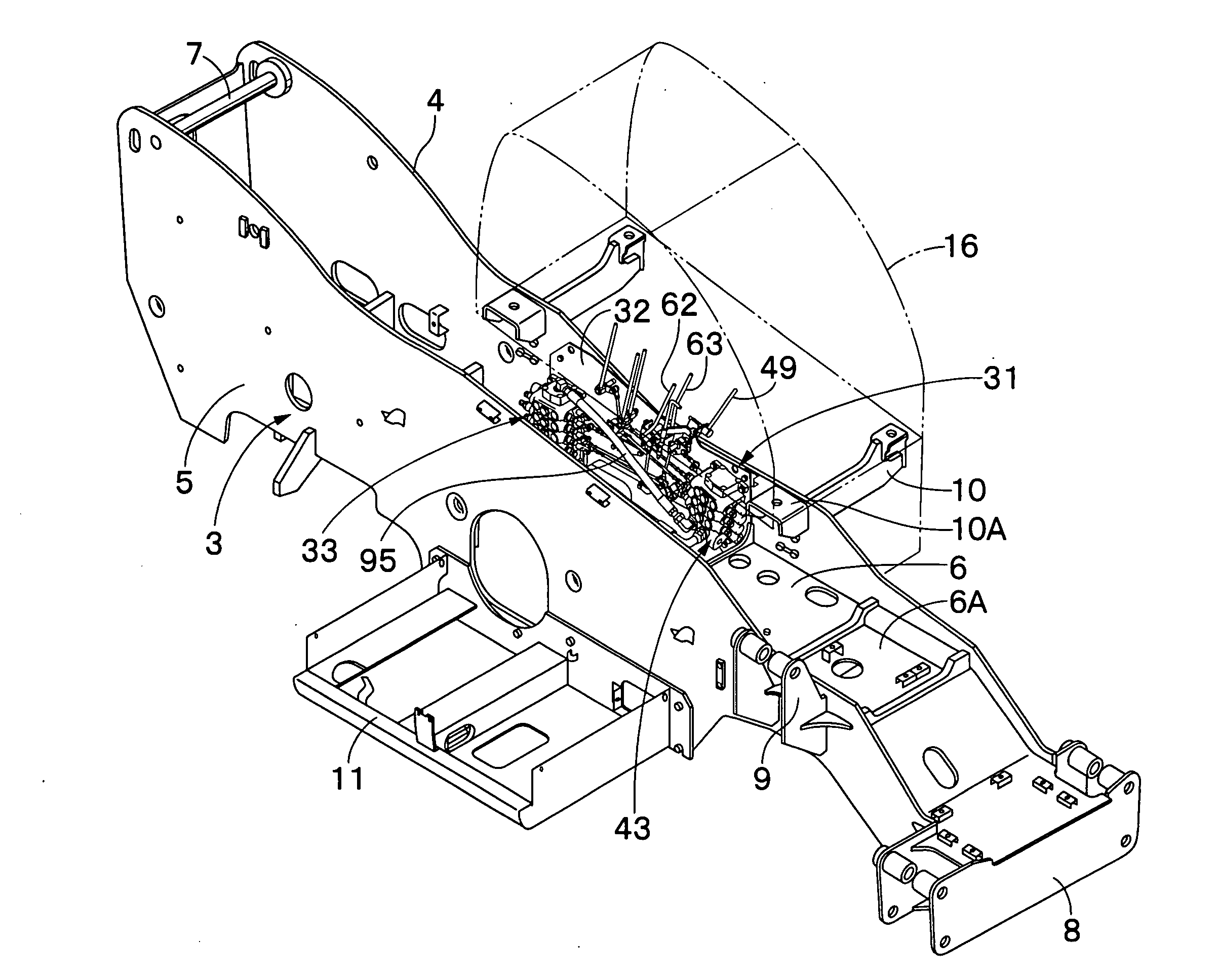
[0060]Reference numeral 3 denotes a frame constituting the base of the vehicle body 2. As shown in FIGS. 4 and 5, this frame 3 serves as a firm support structure member by employing, for example, a pair of vertical plates 4, 5 (a left vertical plate 4, a right vertical plate 5), which are formed of thick steel plates, and which are separated to the left and right sides and extended to the front and rear direction, and a bottom plate 6, which is formed of a thick plate same as the vertical plates 4, 5, and which couples (bonds) the vertical ...

second embodiment

[0215]In the explanation for the second embodiment, the directional control valves 106 to 109, 113 to 115 have been regarded as a hydraulic pilot type directional control valve, and the pilot operating valves 116, 119, 120, 125, 128, 129 have been employed as example signal output means. However, the present invention is not limited to this, and directional control valves, for example, may be proportional solenoid control valves, and electric levers may be employed as signal output means.

[0216]In addition, in the explanation for the first embodiment, the link mechanisms 50, 53, 54, 56, 59 to 61 have been employed as example operation transmission members for the lever / valve assembly 31. However, the present invention is not limited to this, and an operation transmission member made of push-pull wire may be employed to transmit the manipulation of the operation levers to the directional control valves.

[0217]Further, in the explanation for the first embodiment, as an example, the comm...


PUM


Abstract

The frame of a vehicle body is constituted by left and right vertical plates and a bottom plate coupling the vertical plates horizontally. In addition, a control valve device and a control valve device including a plural number of directional control valves are mounted in advance on a single mounting plate together with a correction lever, a plural number of operation levers and link mechanisms to obtain a lever/valve assembly. Then, the mounting plate constituting of the lever/valve assembly is attachable to or detachable from the left vertical plate of the frame by using bolts or the like. As a result, the efficiency of the assembly operation can be improved.

Description

TECHNICAL FIELD[0001]The present invention relates to a working machine, such as a hydraulic excavator, a crane or a lift truck, and relates particularly to a working machine that is designed for the operation of a boom apparatus so called a front, operated by hydraulics to perform a construction or a loading operation.BACKGROUND ART[0002]Generally, a working machine, such as a lift truck, is used for an operation (a loading operation) for delivering freight goods from the ground level to a higher level. Thus, a working machine of this type is constituted by a mobile vehicle frame and a telescopic boom apparatus, which is mounted on the rear portion of the frame so as to be capable of be lifted up and down, and which is extended or retracted by a hydraulic actuator for a boom (for example, Japanese Patent No. 2559831).[0003]Further, the vehicle frame are provided for a directional control valve and operating lever. And the directional control valve is connected to the hydraulic actu...

Claims


Application Information

Patent Timeline
IPC IPC(8): B66C13/12B66C13/56B66F9/065B66F9/22E02F9/16E02F9/20E02F9/22
CPCB66C13/56B66F9/065B66F9/22E02F9/2004E02F9/22
Inventor KAMIYA, SHOUHEISORATA, HIDEOMATSUSHITA, MAKOTOTOYOOKA, TSUKASA
Owner NIHON KENKI CO LTD
Why Eureka
Try Eureka