Current sensor and method of manufacturing current sensor

a current sensor and sensor technology, applied in the field of current sensor and manufacturing current sensors, can solve the problems of difficult to say that the detection sensitivity and the responsiveness have it is difficult to say that they have sufficiently reached the stable performance level, so as to achieve high precision, high precision and stability, and efficient manufacturing

Active Publication Date: 2008-12-25
TDK CORPARATION
View PDF1 Cites 35 Cited by
  • Summary
  • Abstract
  • Description
  • Claims
  • Application Information

AI Technical Summary

Benefits of technology

[0027]Further, when the support member supporting the first and the second magnetoresistive elements (or the first to the fourth magnetoresistive elements) is provided, the support member has the reference plane facing outward, the reference plane being located in parallel to the stack surfaces of the stacked structures of the first and the second magnetoresistive elements (or the first to the fourth magnetoresistive elements), and, the relative position of the conductor and each of the first and the second current sensors of the present invention may more be easily and precisely defined. Thereby, the detection of the current to be detected may be simply performed.
[0028]Also, according to the method of manufacturing the first and the second current sensors of the present invention, the current sensor having a detection performance of the high precision as described above may be efficiently manufactured.
[0029]According to the first and the second current sensors of the present invention, when the bias magnetic fie

Problems solved by technology

However, with the miniaturization, even the magnetic sensor and the current sensor using GMR elements are likely influenced by noise from external (unnecessary magnetic field, or the like), and thus an improvement in stability of the detection sensitivity and the respon

Method used


Image

  • Current sensor and method of manufacturing current sensor
  • Current sensor and method of manufacturing current sensor
  • Current sensor and method of manufacturing current sensor

Examples


first embodiment

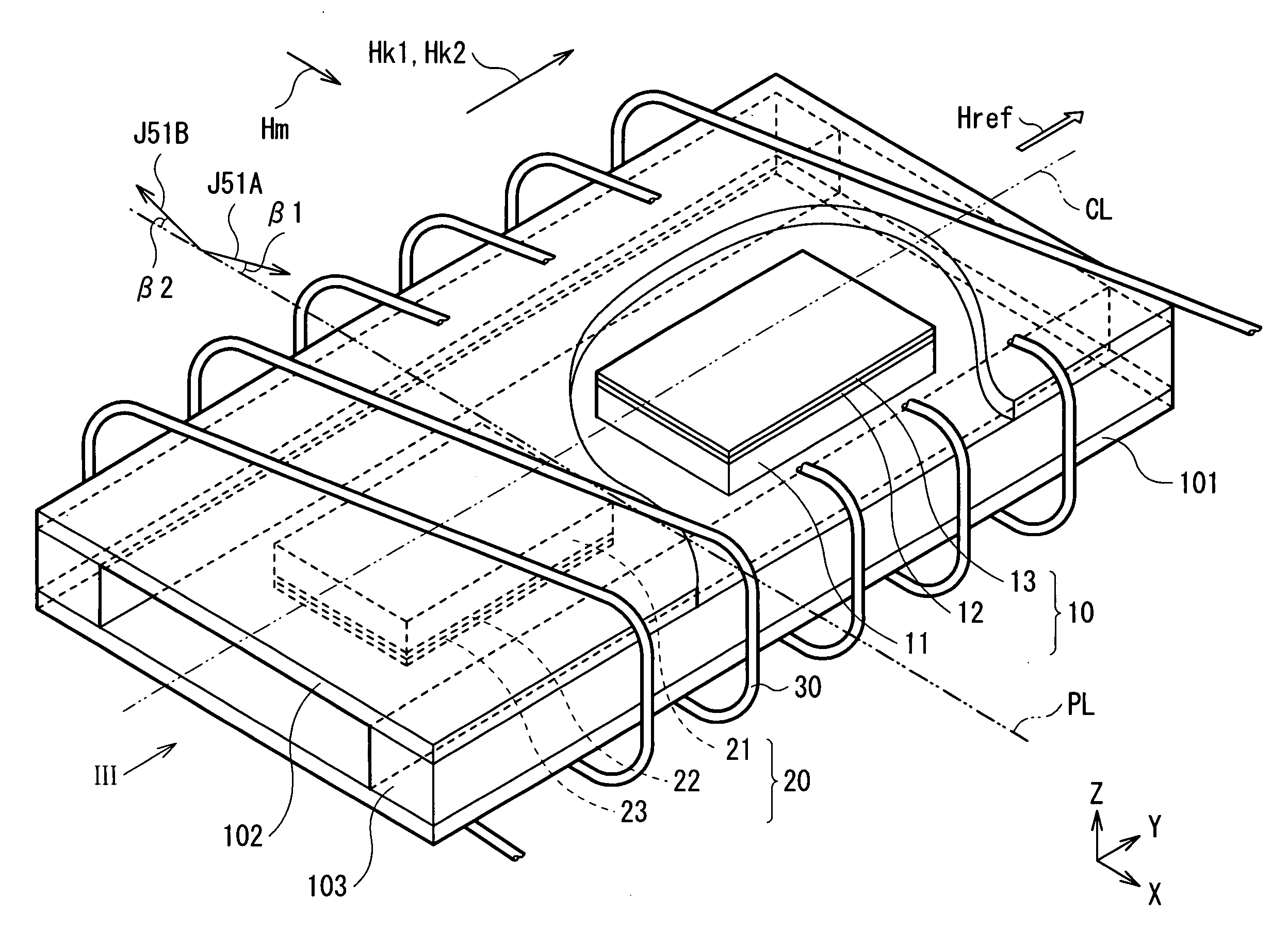
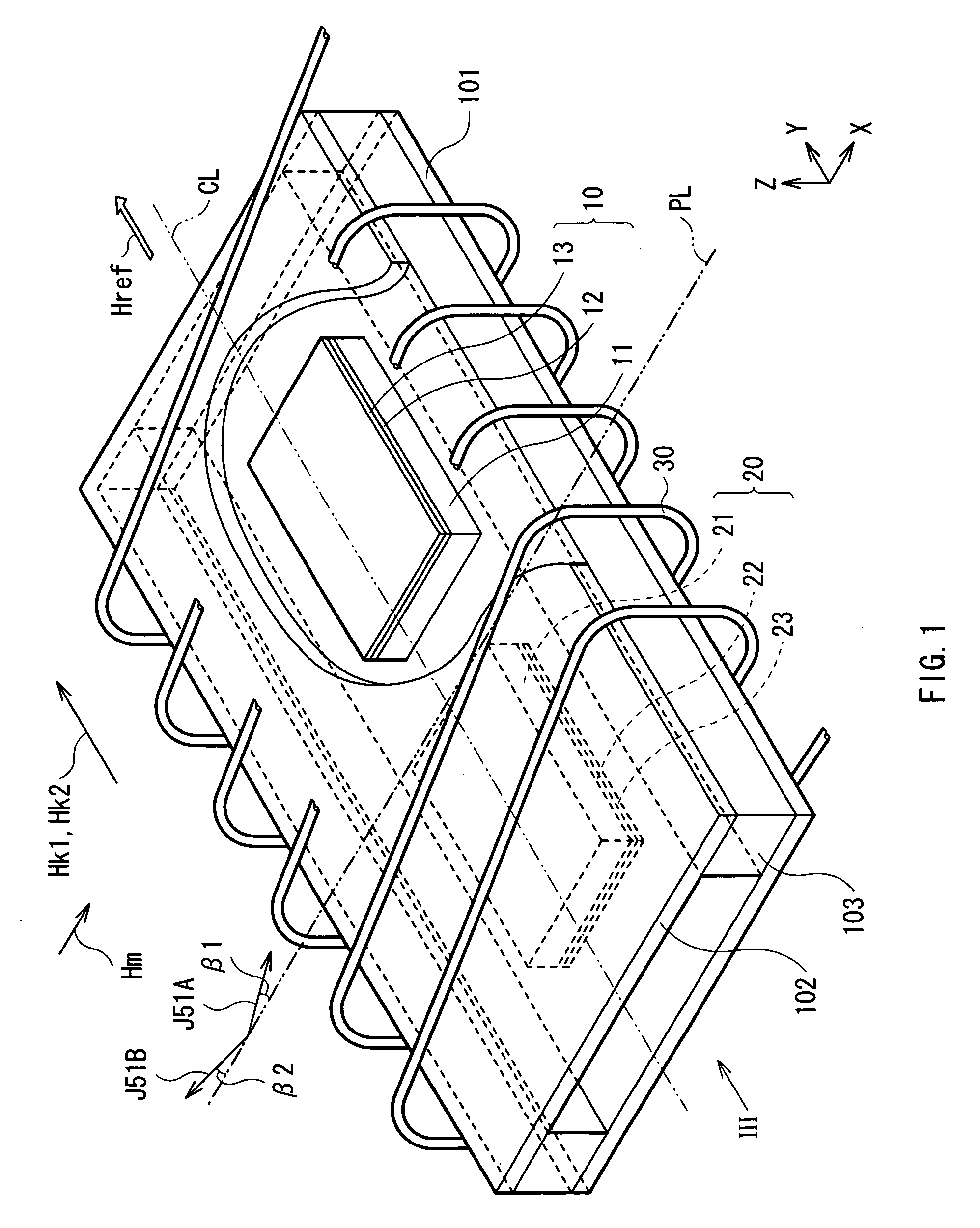
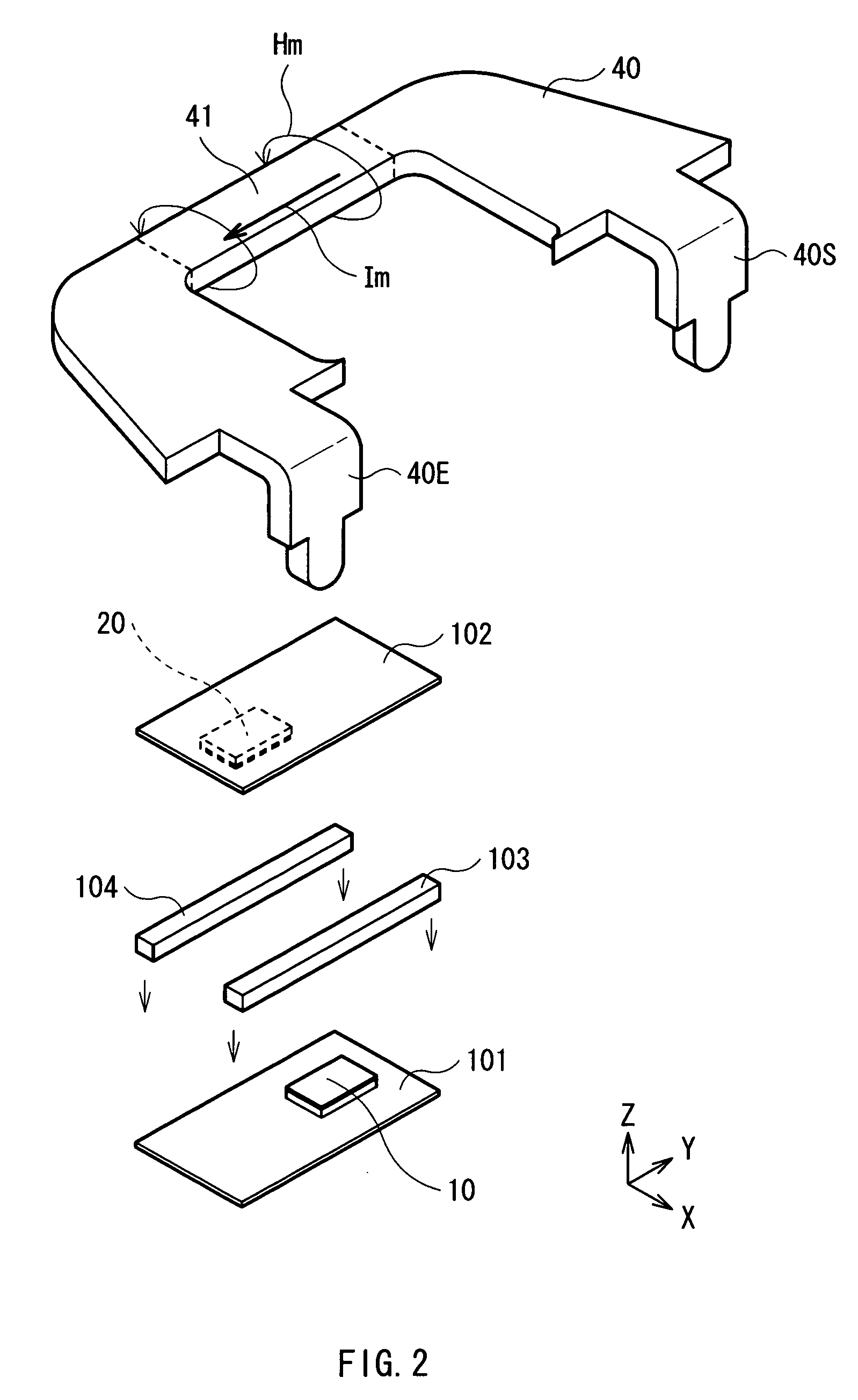
[0051]First, with reference to FIGS. 1, 2, 3A and 3B, an overall configuration of a current sensor in a first embodiment of the present invention will be described. FIG. 1 is fracture view partially showing a perspective configuration of the current sensor of the first embodiment. FIG. 2 is an exploded perspective view of FIG. 1. FIG. 2 also illustrates a conductor 40 to which a current to be detected Im is supplied, and shows a positional relationship between the current sensor and the conductor 40. Also, FIG. 3A is a configuration view as viewed from the direction of arrow III of FIG. 1. FIG. 3B is a cross-sectional view including a first module 10 and a second module 20 which will be described later. Meanwhile, in FIGS. 1, 3A and 3B, the conductor 40 which will be described later is omitted, and in FIGS. 2, 3A and 3B, a coil 30 which will be described later is omitted.

[0052]The current sensor includes the first module 10 and the second module 20. The current sensor is disposed in...

second embodiment

[0096]Next, the configuration of a current sensor in a second embodiment of the present invention will be described. The current sensor of the second embodiment has the configuration similar to that of the first embodiment, except that the configurations of the first module 10 and the second module 20 are different. Therefore, the difference from the current sensor of the first embodiment will be mainly described, and thereby the description of the other parts is appropriately omitted.

[0097]FIGS. 16 and 17 are outline views showing the perspective configurations of the first module 10 and the second module 20, respectively, in the current sensor of the second embodiment.

[0098]The current sensor of the first embodiment is configured by the two MR elements (MR elements 5A and 5B) and the two constant current sources (constant current sources CG1 and CG2). On the other hand, the current sensor of the second embodiment is configured by four MR elements (MR elements 5A to 5D).

[0099]As sh...


PUM


Abstract

Provided is a current sensor capable of detecting an induced magnetic field by a current to be detected with higher precision. The first and second modules are provided on facing surfaces of integrated substrates, respectively, with spacers in between. Each of the first and second modules includes an element substrate, and an MR element layer. On each of the MR elements layers, provided is an MR element having a stacked structure including a pinned layer, a nonmagnetic intermediate layer, and a free layer whose magnetization direction changes according to the induced magnetic field and which exhibits an anisotropic field in a direction different from that of the magnetization of the pinned layer. The stacked structures of the MR elements are provided in a same layer level.

Description

CROSS REFERENCES TO RELATED APPLICATIONS[0001]The present invention contains subject matter related to Japanese Patent Application JP 2007-166576 filed in the Japanese Patent Office on Jun. 25, 2007, the entire contents of which being incorporated herein by reference.BACKGROUND OF THE INVENTION[0002]1. Field of the Invention[0003]The present invention is related to a current sensor capable of detecting a change of a current flowing through a conductor with high precision, and a method of manufacturing such a current sensor.[0004]2. Description of the Related Art[0005]Generally, for an accurate measurement of a control current flowing through a circuit of a control device, there is used a method where a resistance is connected in series to a circuit so as to measure a voltage drop of the resistance. However, in this case, a load other than a lord of the control system is added, and thus the control system may be adversely influenced in some way. For this reason, there is used a metho...

Claims


Application Information

Patent Timeline
IPC IPC(8): G11B5/33
CPCB82Y25/00G01R15/205G01R33/093H01F10/3268H01F17/0033
Inventor SHOJI, SHIGERU
Owner TDK CORPARATION
Why Eureka
Try Eureka