Soft-switching circuit for power supply

a power supply and circuit technology, applied in the direction of electric variable regulation, process and machine control, instruments, etc., can solve the problems of large switching loss and magnetic interference, and achieve the effect of low switching loss, low conducting loss and reduced conducting loss

Inactive Publication Date: 2008-12-25
LEAD YEAR ENTERPRISE
View PDF8 Cites 41 Cited by
  • Summary
  • Abstract
  • Description
  • Claims
  • Application Information

AI Technical Summary

Benefits of technology

[0007]It is a primary object of the present invention to provide a soft-switching circuit for a power supply that connects an auxiliary circuit to a bridgeless rectifier circuit to allow the main switches and the auxiliary switch to accomplish zero voltage switching and zero current switching respectively for providing low conducting loss and low switching loss.
[0008]It is a secondary object of the present invention to provide a soft-switching circuit for a power supply that removes a bridge rectifier from an input terminal by providing a bridgeless rectifier circuit to reduce conducting loss and to provide the circuit with low conducting loss.
[0009]In order to achieve the foregoing objects, a soft-switching circuit for a power supply of the present invention is comprised of a bridgeless rectifier circuit and an auxiliary circuit. The auxiliary circuit is connected to the bridgeless rectifier circuit, which comprises at least one filtering inductor, two main switches, two diodes and a capacitor. The filtering inductor is connected to the first diode. The first diode is connected to the second diode. The second diode is connected to the first main switch. The first main switch is connected to the second main switch. The two diodes and the two main switches are connected in parallel with the capacitor to reduce conducting loss. The auxiliary circuit comprises at least one resonant inductor, an auxiliary switch, at least two diodes and a voltage source circuit. The diodes are connected to the resonant inductor and further connected to the voltage source circuit. The voltage source circuit is connected to the auxiliary switch, whereby the soft-switching circuit can accomplish zero voltage switching and zero current switching to provide low conducting loss and low switching loss.

Problems solved by technology

However, the power converters shown in both FIG. 1 and FIG. 2 have larger switching loss and magnetic interference when they are operated in high frequency.

Method used


Image

  • Soft-switching circuit for power supply
  • Soft-switching circuit for power supply
  • Soft-switching circuit for power supply

Examples


Embodiment Construction

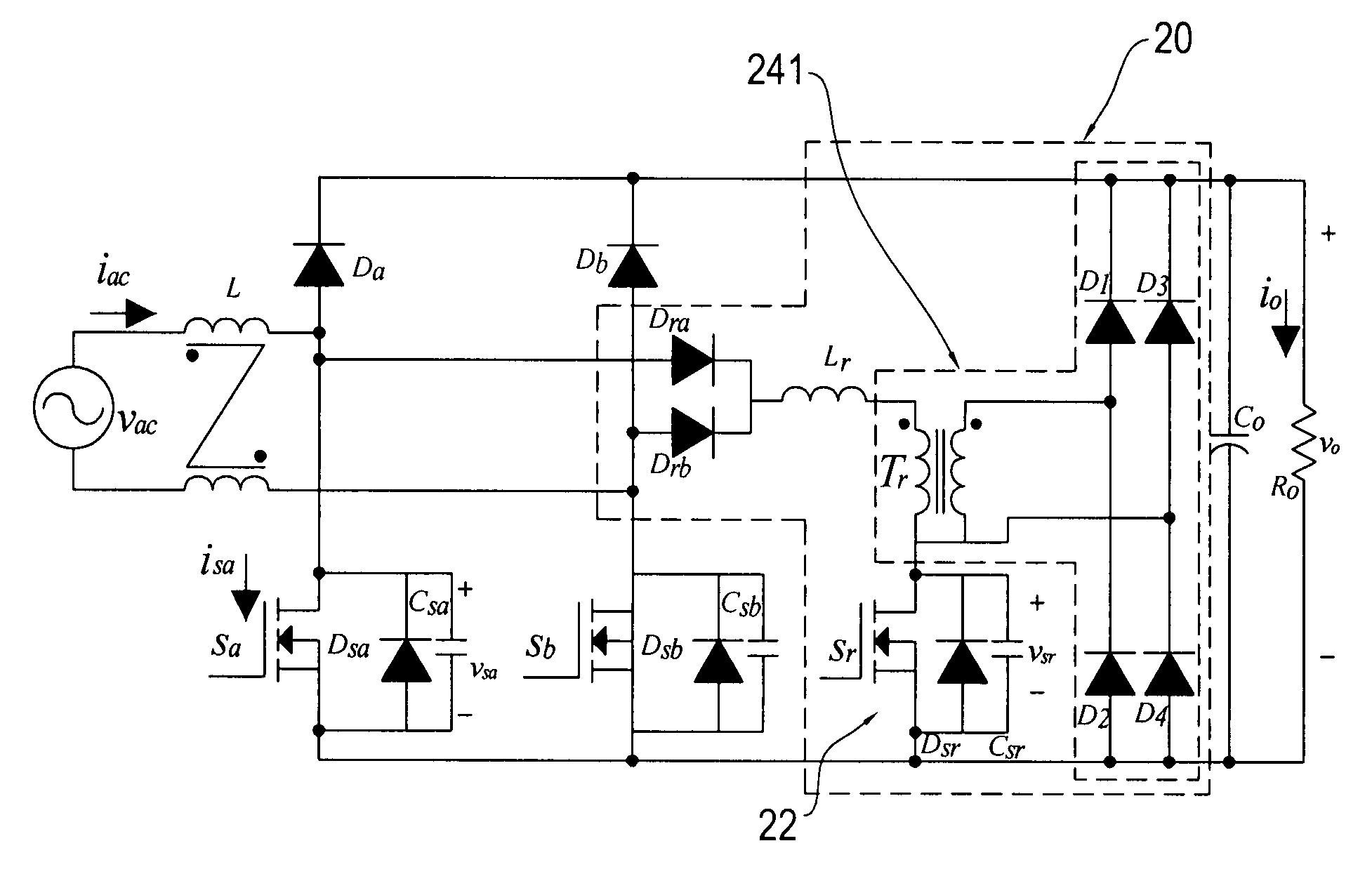
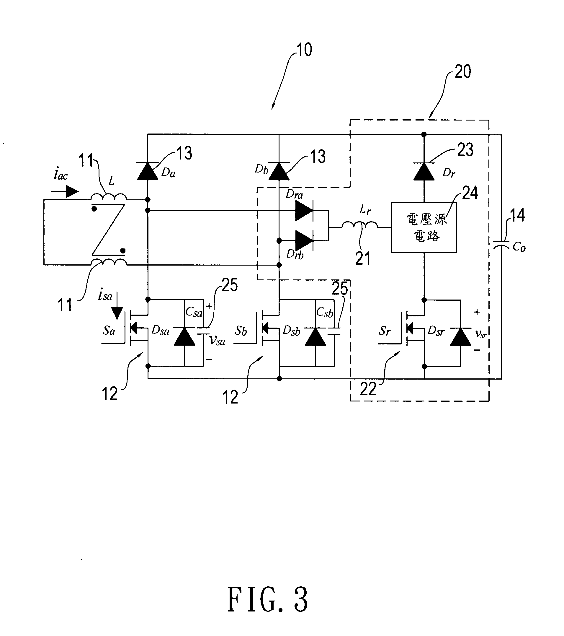
[0022]Referring to FIG. 3, a soft-switching circuit for a power supply of the present invention generally comprises a bridgeless rectifier circuit 10 and an auxiliary circuit 20. The auxiliary circuit 20 is connected to the bridgeless rectifier circuit 10. The bridgeless rectifier circuit 10 comprises at least one filtering inductor 11, two main switches 12, two diodes 13 and a capacitor 14. The filtering inductor 11 is connected to the first diode 13. The filtering inductor 11 is a coupled filtering inductor or an uncoupled filtering inductor. The first diode 13 is connected to the second diode 13. The second diode 13 is connected to the first main switch 12. The first main switch 12 is connected to the second main switch 12. The diodes 13 and the main switches 12 are connected in parallel with the capacitor 14 so that a bridge rectifier can be removed from an input terminal to reduce conducting loss. The auxiliary circuit 20 comprises at least one resonant inductor 21, an auxiliar...


PUM


Abstract

A soft-switching circuit for a power supply comprises a bridgeless rectifier circuit and an auxiliary circuit. The auxiliary circuit is connected to the bridgeless rectifier circuit, which comprises at least one filtering inductor, two main switches, two diodes and a capacitor. The filtering inductor is connected to the first diode. The first diode is connected to the second diode. The second diode is connected to the first main switch. The first main switch is connected to the second main switch. The diodes and the main switches are connected in parallel with the capacitor to reduce conducting loss. The auxiliary circuit comprises at least one resonant inductor, an auxiliary switch, at least two diodes and a voltage source circuit. The diodes are connected to the resonant inductor and further connected to the voltage source circuit. The voltage source circuit is connected to the auxiliary switch, whereby the soft-switching circuit can accomplish zero voltage switching and zero current switching to provide low conducting loss and low switching loss.

Description

FIELD OF THE INVENTION[0001]The present invention relates to a soft-switching circuit for a power supply that connects an auxiliary circuit to a bridgeless rectifier circuit to accomplish the soft switching with zero voltage transition for reducing switching loss and simultaneously providing low conducting loss and low switching loss which suitable for use in a power supply or the like.BACKGROUND OF THE INVENTION[0002]Due to the development of technology, the power has wider applications. The power supplies are indispensable to more and more products. For example, personal computers, industrial computers, switches, printers and so forth require respective AC / DC converters to turn on the power source.[0003]Most existing power supplies employ boost-type power converter that employ power factor correction. The boost-type power converter transforms AC current into DC current by a bridge rectifier, and it is operated in a boost-type converter mode. It has two operation states. In first s...

Claims


Application Information

Patent Timeline
Patent Type & Authority Applications(United States)
IPC IPC(8): H02M3/335H02M7/06
CPCH02M3/335H02M7/217Y02B70/1433Y02B70/1441H02M1/0085Y02B70/10
Inventor TSAI, HSIEN-YICHEN, DANHSIA, TSUN-HSIAO
Owner LEAD YEAR ENTERPRISE
Why Eureka
Try Eureka