Fuser assembly having oil retention features

a technology of oil retention and assembly, which is applied in the field of electrographic imaging devices, can solve the problems of thicker film thickness, high friction force, and higher friction force and driving torqu

Inactive Publication Date: 2008-12-25
LEXMARK INT INC
View PDF2 Cites 24 Cited by
  • Summary
  • Abstract
  • Description
  • Claims
  • Application Information

AI Technical Summary

Problems solved by technology

The sliding contact between the belt and the heater surface can cause a high friction force.
However, the higher viscosity of grease can cause a higher friction force and driving torque, and a thicker film thickness, and in turn can cause a lower fusing grade/quality.
On the other hand, oil as lubricant has a lower viscosity than grease and can form a thinner film, resulting in lower driving torque and b

Method used


Image

  • Fuser assembly having oil retention features
  • Fuser assembly having oil retention features
  • Fuser assembly having oil retention features

Examples


Embodiment Construction

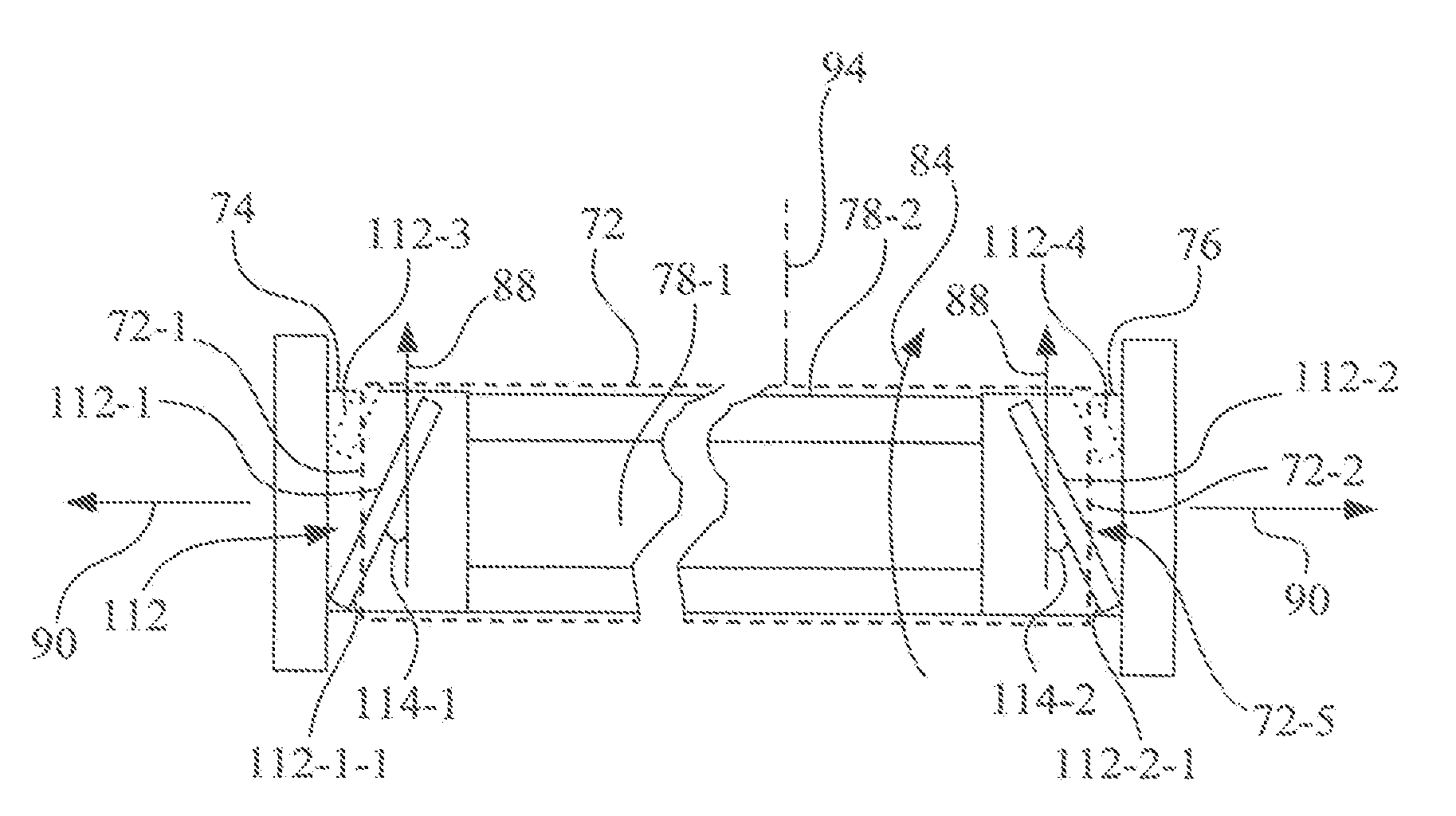
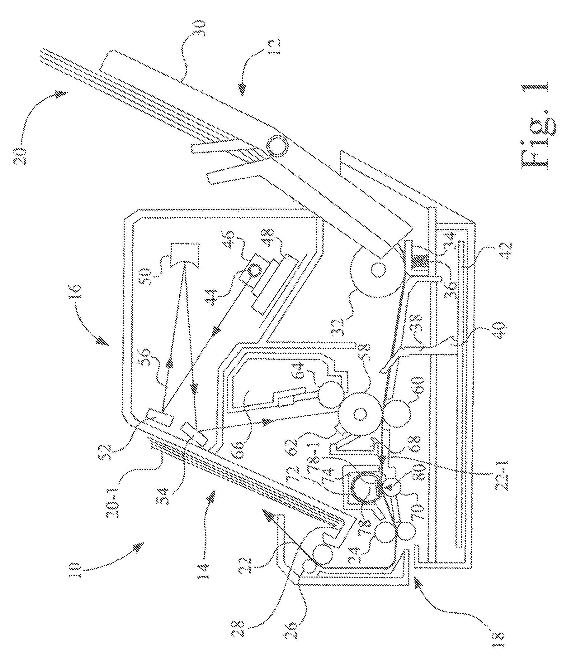
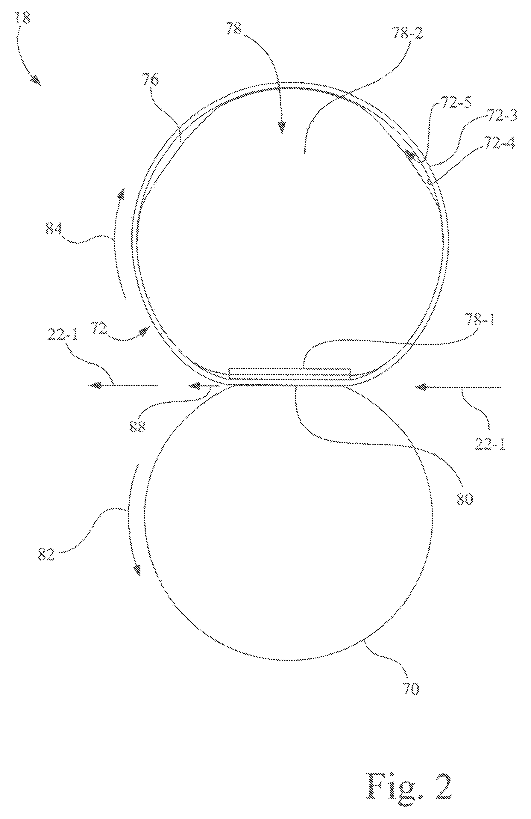
[0027]Referring now to the drawings and particularly to FIG. 1, there is shown an exemplary electrophotographic imaging apparatus 10, e.g., a laser printer and / or copier, configured in accordance with an embodiment of the present invention. Imaging apparatus 10 includes a media feed section 12, an image-forming device 14, a laser scanning device 16, and a fuser assembly 18.

[0028]Media feed section 12 sequentially transports a sheet of print media (e.g., paper) 20-1 from a stack of sheets of print media 20 to image-forming device 14. Each sheet of print media 20-1 moves along a media feed path 22 in a sheet feed direction 22-1. Image-forming device 14 transfers a toner image to the transported sheet of print media 20-1. Fuser assembly 18 fixes the toner image to the sheet of print media 20-1 sent from image-forming device 14. Thereafter, the sheet of print media 20-1 is ejected out of imaging apparatus 10 by media transport rollers 24, 26 and into output tray 28.

[0029]In the exemplar...


PUM


Abstract

A fuser assembly includes a first end cap, and a second end cap spaced apart from the first end cap along an axis orthogonal to a sheet feed direction. A fuser belt is positioned between and supported by the first end cap and the second end cap to rotate around the axis in a belt moving direction at the nip corresponding to the sheet feed direction. A heater assembly is located in the hollow interior of the fuser belt. A plurality of ribs is positioned to contact the interior surface of the fuser belt. A first rib is connected to one of the first end cap and the heater assembly. A second rib is connected to one of the second end cap and the heater assembly. Each of the plurality of ribs is oriented to longitudinally extend at an acute angle with respect to the belt moving direction.

Description

CROSS-REFERENCE TO RELATED APPLICATIONS[0001]None.MICROFICHE APPENDIX[0002]None.GOVERNMENT RIGHTS IN PATENT[0003]None.BACKGROUND OF THE INVENTION[0004]1. Field of the Invention[0005]The present invention relates to electrophotographic imaging devices, and, more particularly, to a fuser assembly having oil retention features.[0006]2. Description of the Related Art[0007]An electrophotographic imaging apparatus, such as a laser printer, forms a latent image on a surface of a photoconductive material by selectively exposing an area of the surface to light. The latent electrostatic image is developed into a visible image by electrostatic toners which contain pigment components and thermoplastic components. The photoconductor may be either positively or negatively charged, and the toner system similarly may contain negatively or positively charged particles. A print medium (e.g., a sheet of paper) or intermediate transfer medium is given an electrostatic charge opposite that of the toner ...

Claims


Application Information

Patent Timeline
IPC IPC(8): G03G15/20
CPCG03G2215/2035G03G15/2025
Inventor ARDERY, JEFFREY ALLENROMAIN, JASON KYLESMITH, JERRY WAYNEWU, FANGSHENG
Owner LEXMARK INT INC
Why Eureka
Try Eureka